A9: The Motion Box
Inspiration and concept
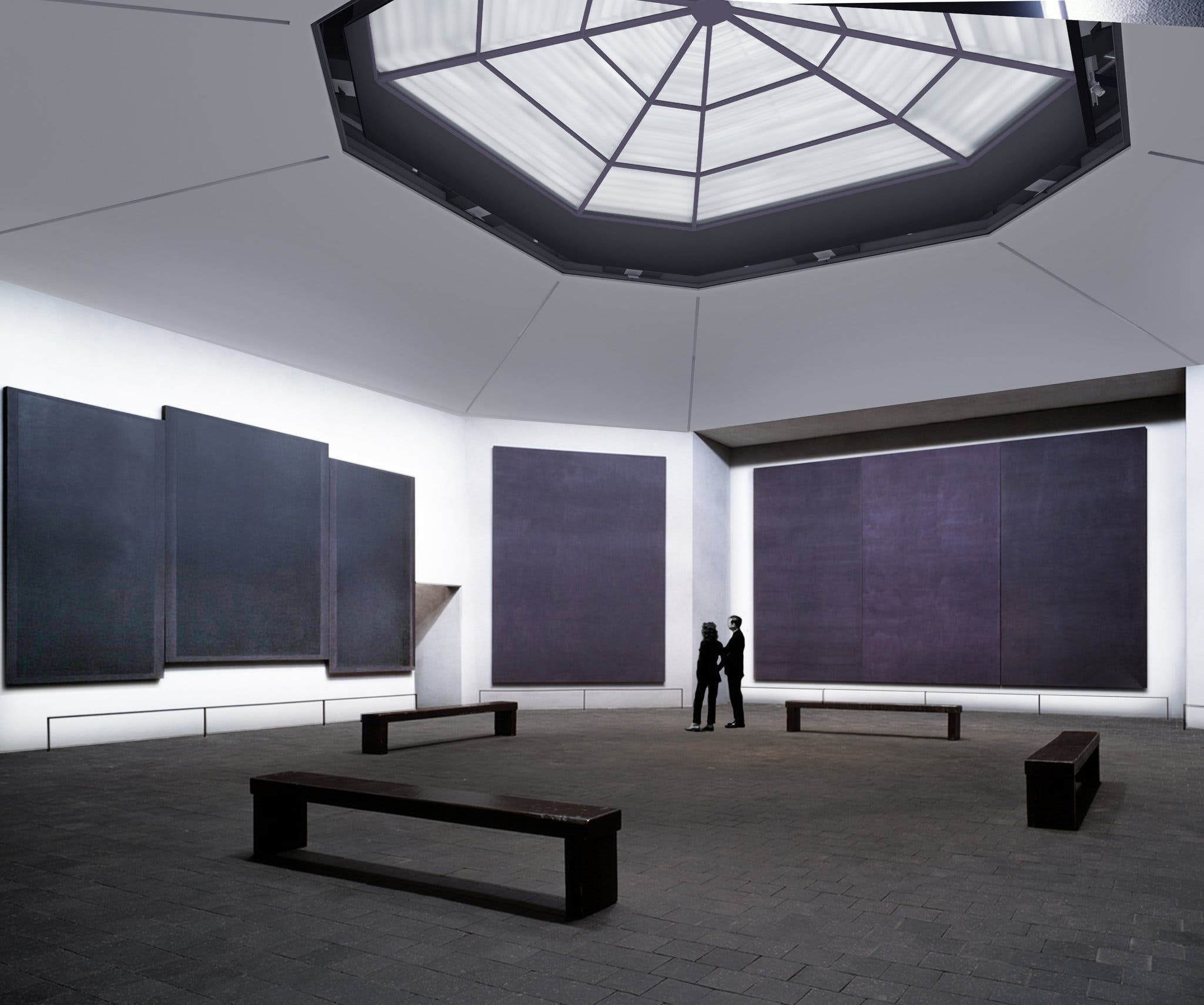
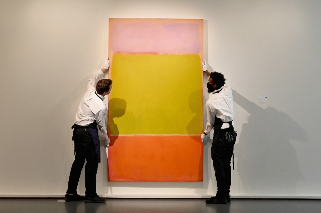
The final project was about systems integration and we had to make something that used most, if not all, the techniques learned in class this quarter. My original idea was to create a light remniscent of Rothko's paintings, and more specifically of the Rothko Chapel, which uses light to create a certain sense of the numinous when viewing the paintings. I've always thought it would be cool if sensors were integrated in this exhibit, where the closer you got to the painting, the brighter the light would get.
Originally I thought of making a resin sheet with lights cast-in-place to create this effect but chose to have little cubic lights instead that I could place all over my apartment. They would light up slowly as I approached and fade as I walked away. My choice of sensor, however, made that interaction difficult: I chose a motion sensor (PIR), which is on/off, and not a distance sensor, which would have enabled me to map the distance values to the brightness of the led.
Techniques used for this project:
1. 3D modeling
2. Circuit design
3. PCB making (milling + surface mount soldering)
4. CNC milling
5. 3D printing
5. Resin casting
6. Programming
The circuit: vital connections
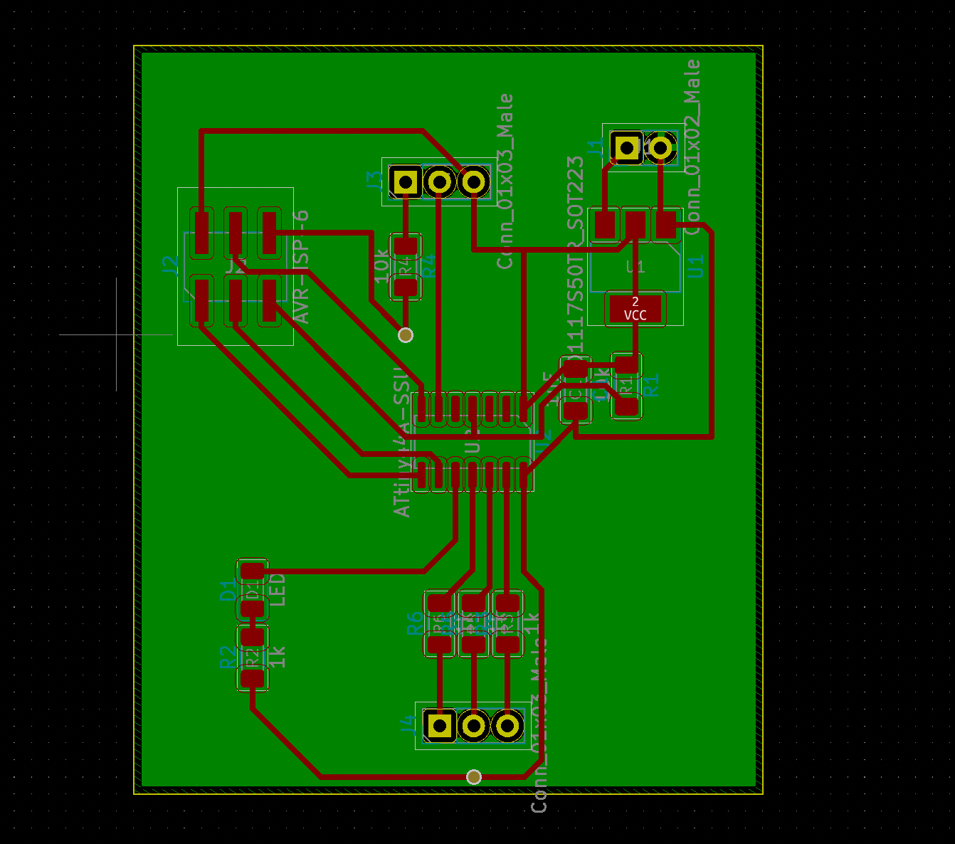
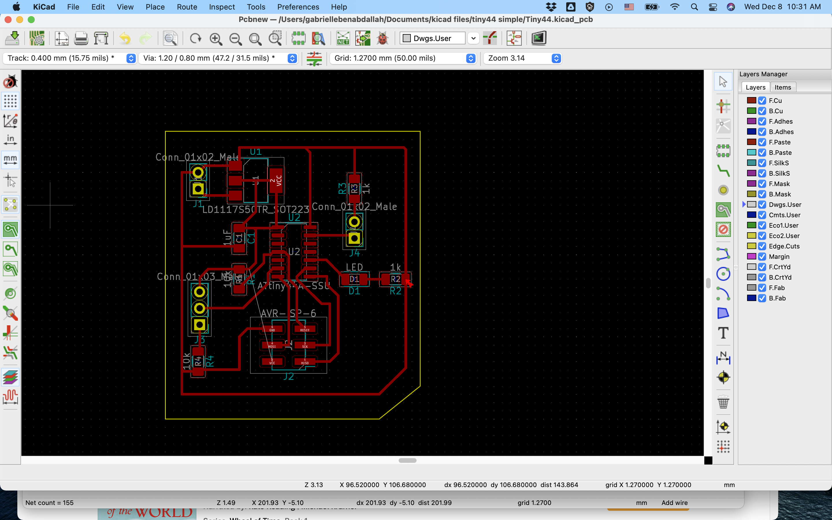
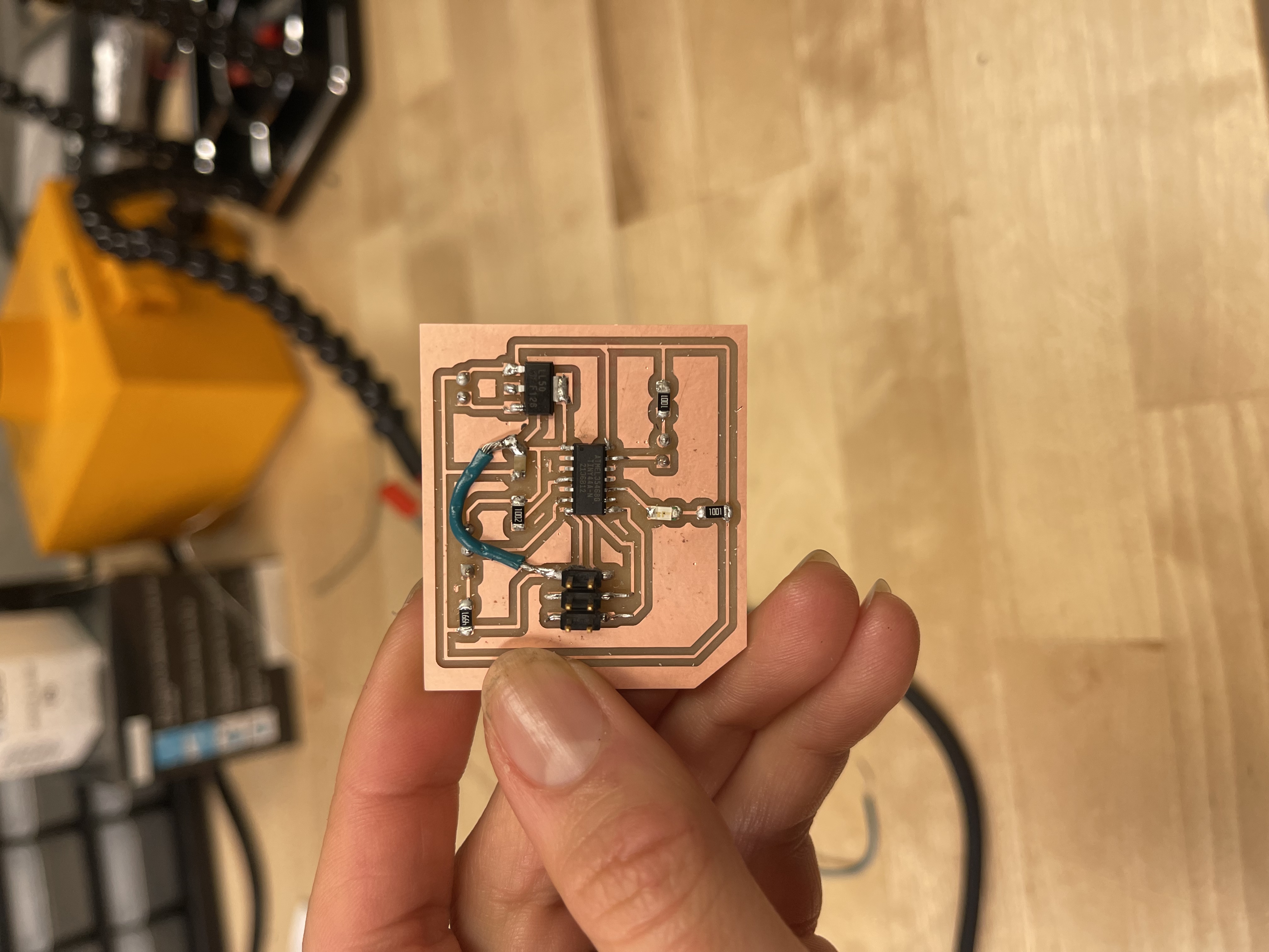
I made two boards for this project. My initial board wasn't sound and I figured that out by comparing it to the reference board. I fixed it using the Nadya-finds-trash-on-the-soldering-station technique, which I later used not as a fix but as a part of my board design.
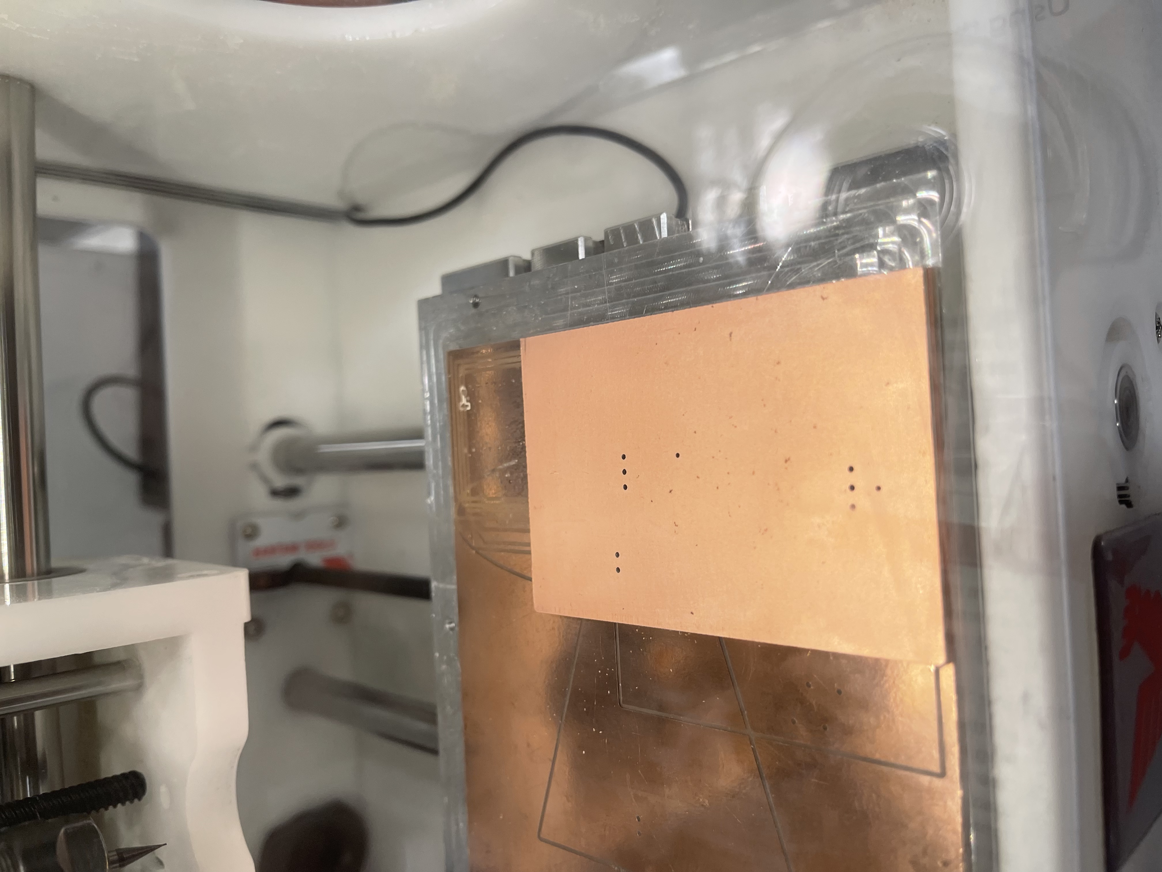
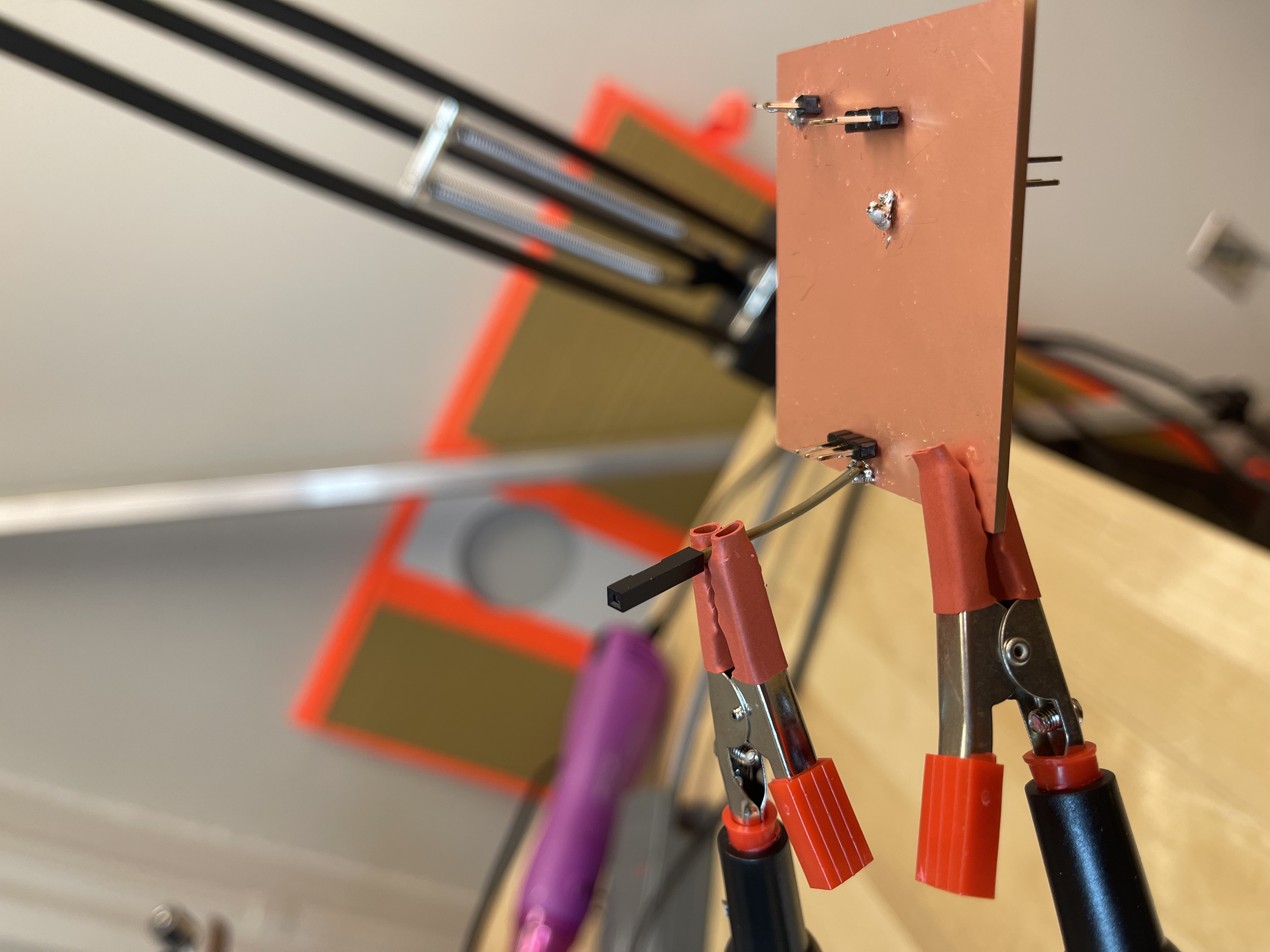
I also had trouble with the double sidedness of my first board (a CAM issue with the Othermill) which led me to create these blobs of solder to secure a good connection to GND. It was successful (the board worked) but flimsy.
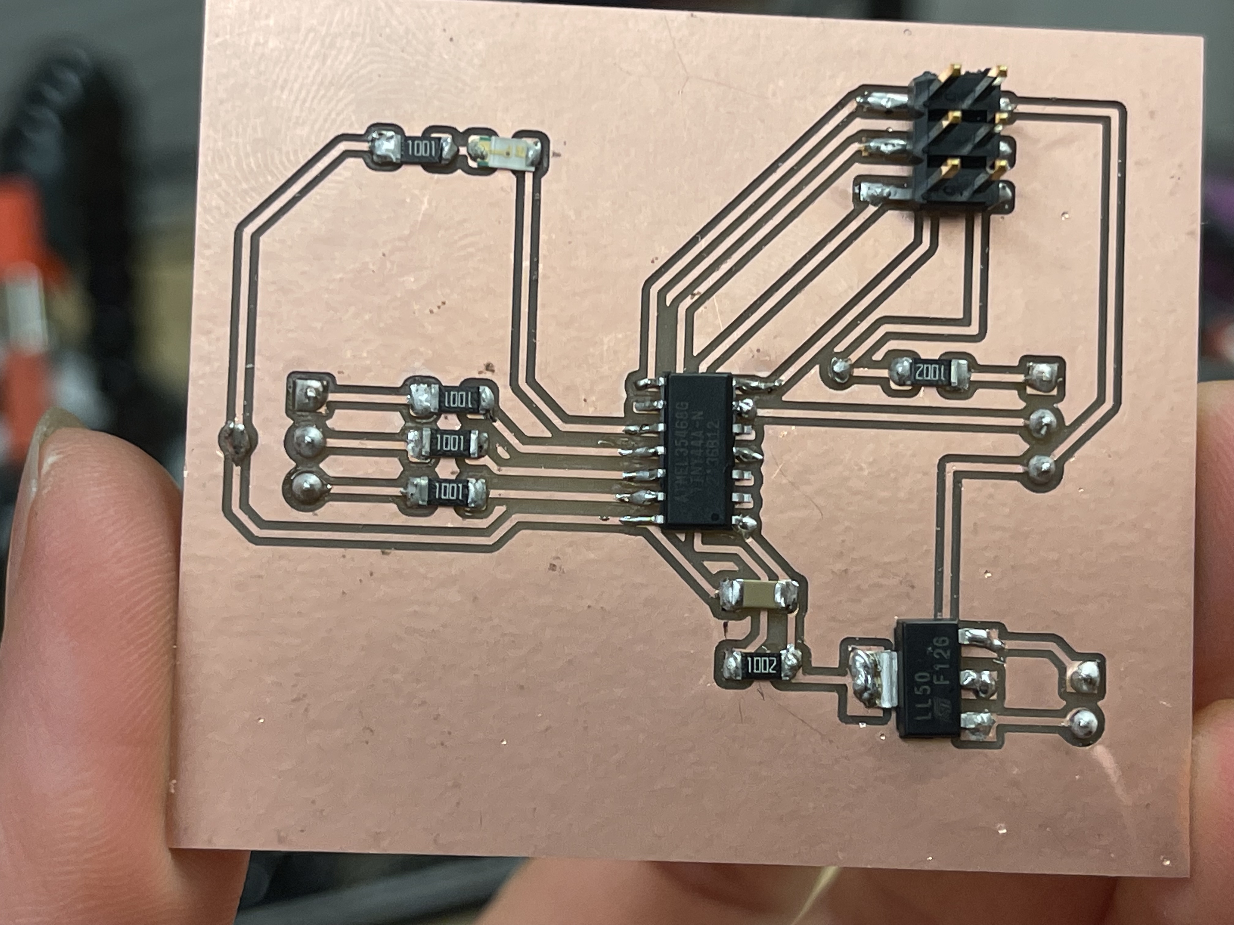
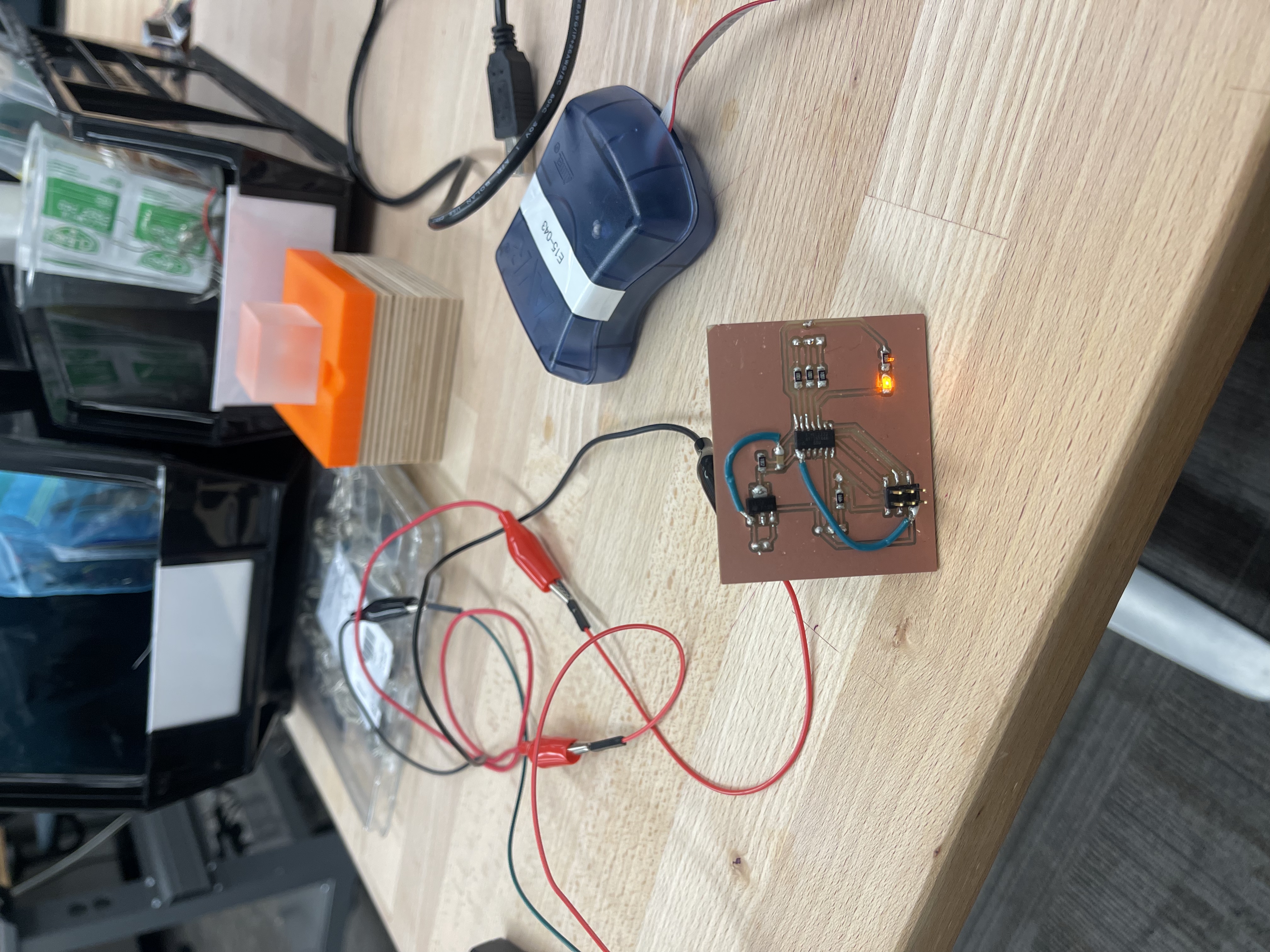
As you can see, some pretty vital connections were missing from V1 of the board.
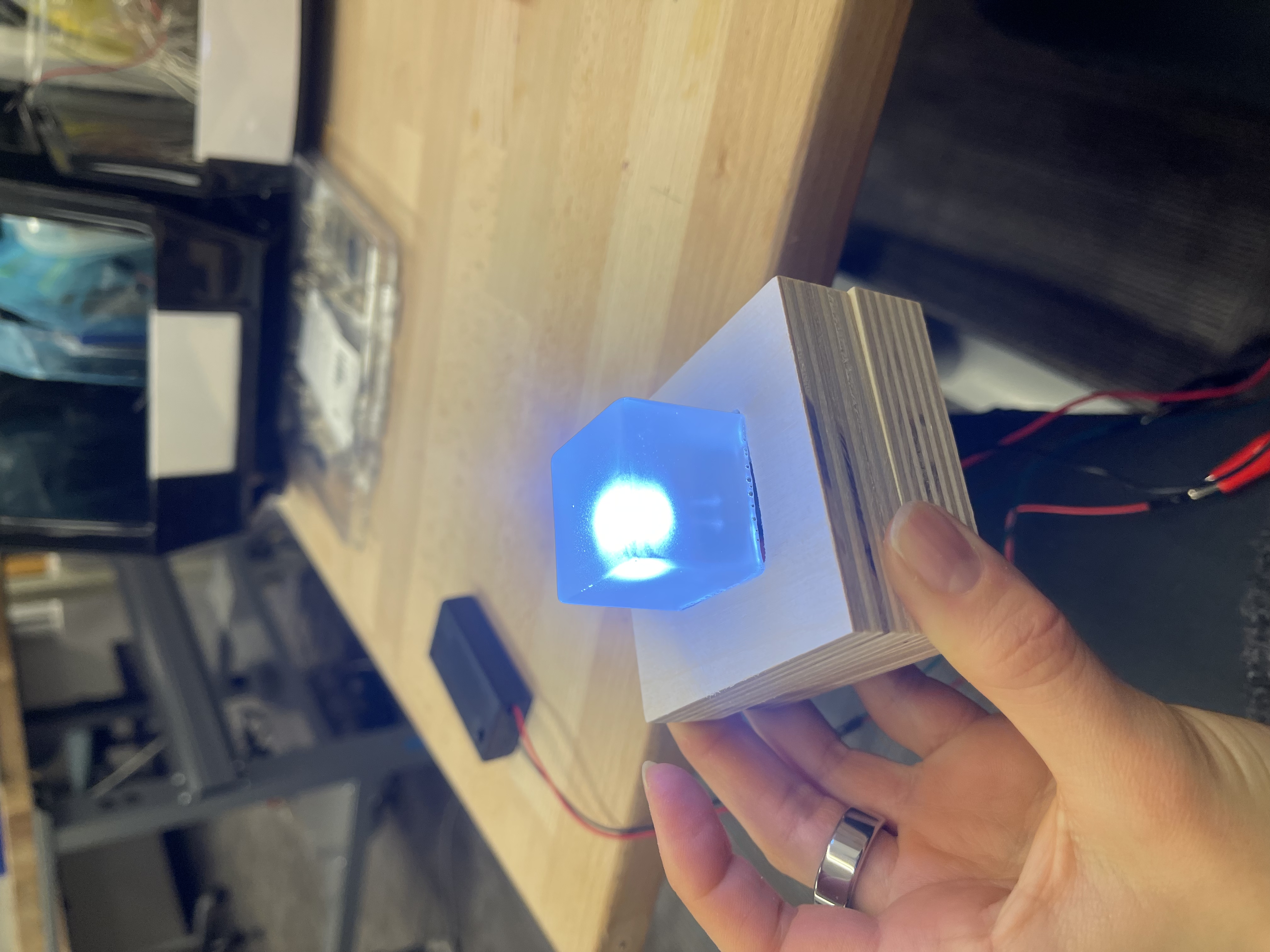
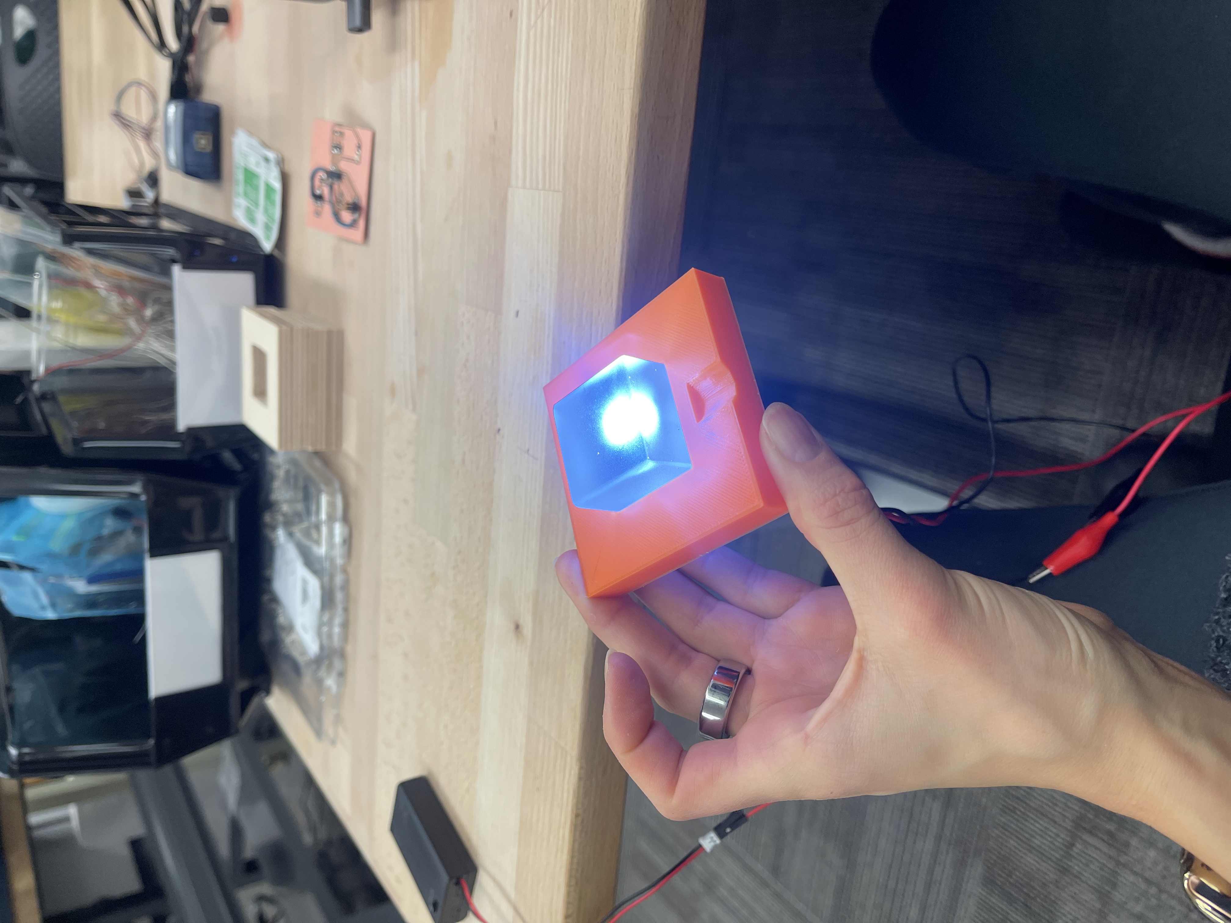
Once fixed, it worked great! Connections were still flimsy though, so I made a new board NOT double sided and purposefully used the NFTSS technique as a hack instead of spending 3 more hours on kicad rerouting traces.
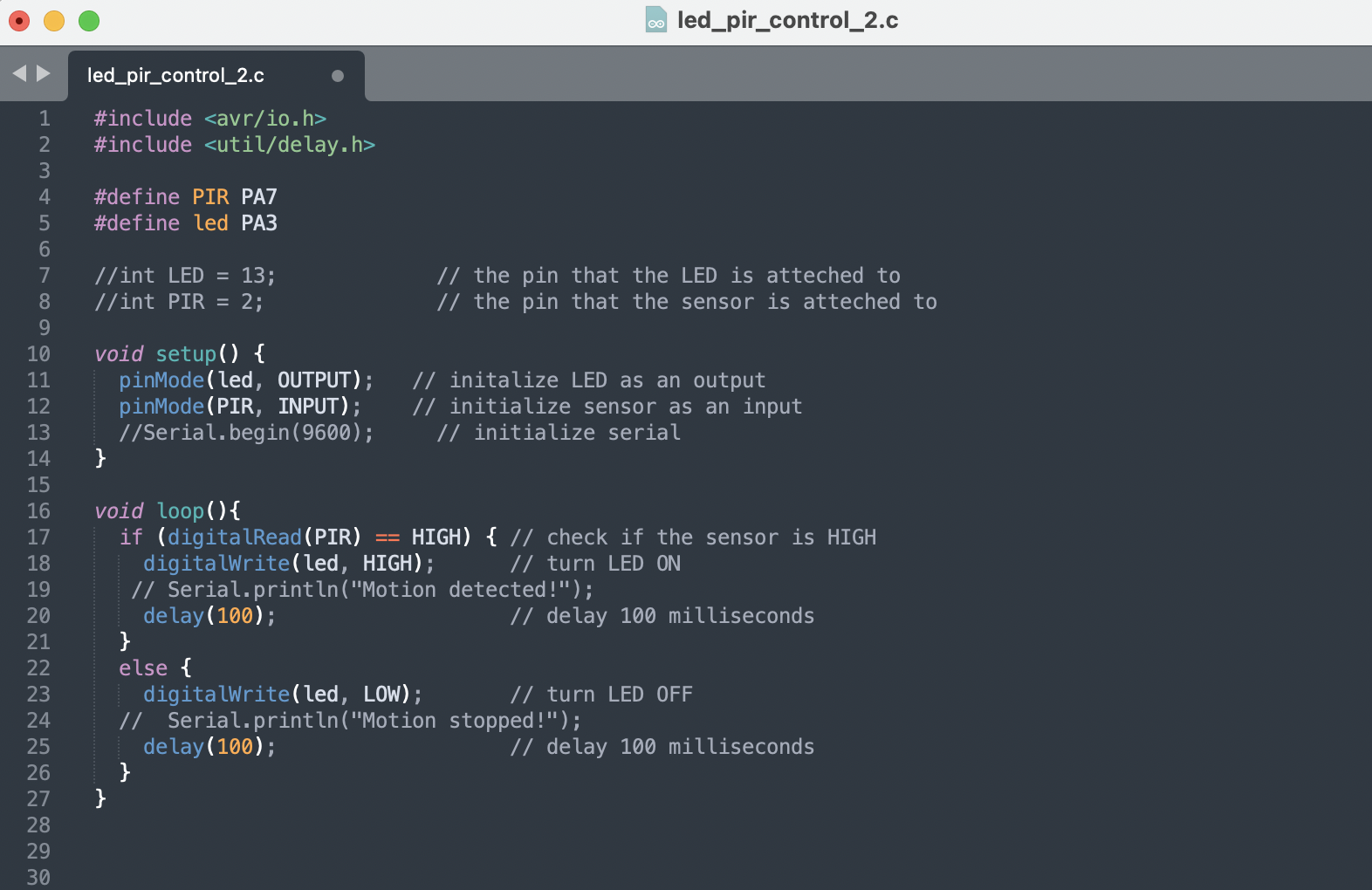
Programming: straighforward
The code is pretty straighforward for this project. Here it is:
The cube: resin casting
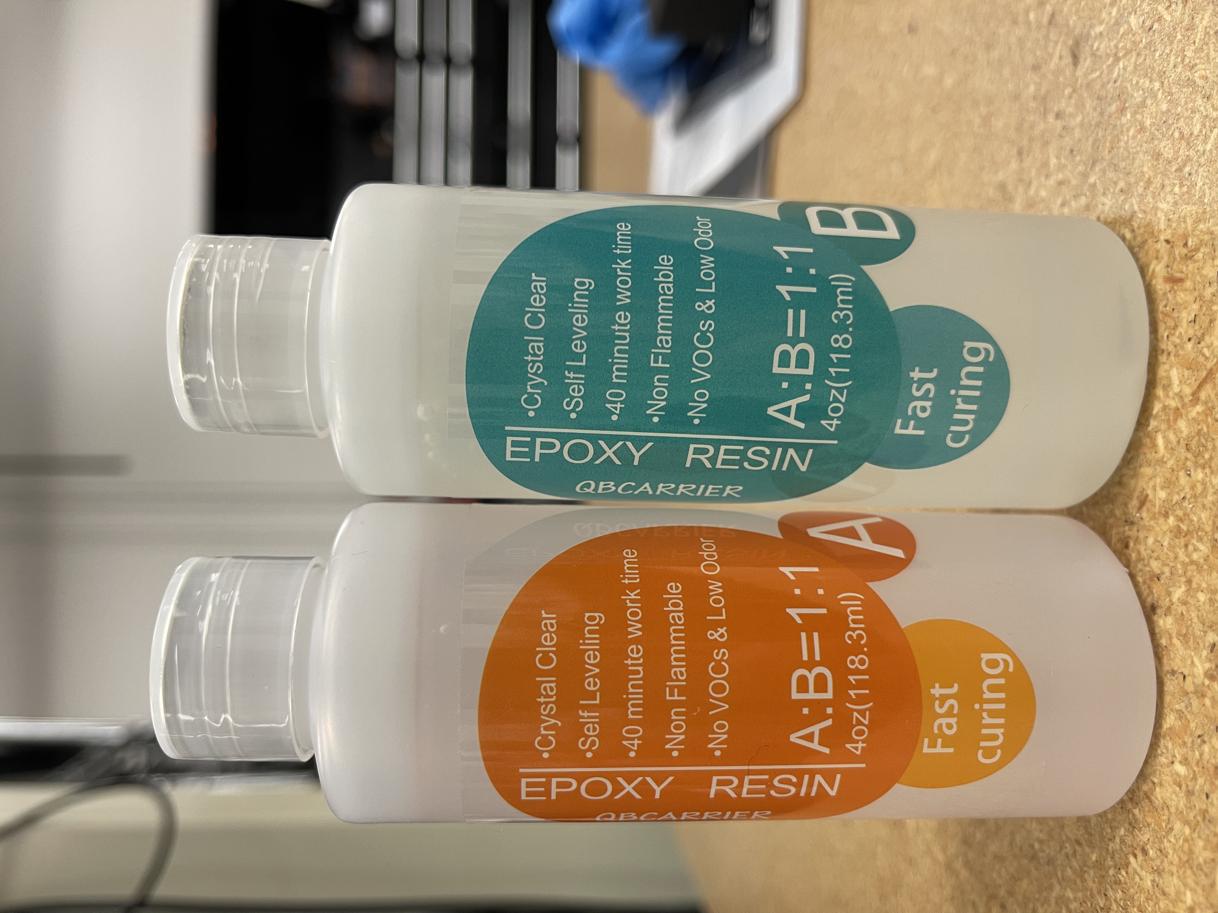
Making the resin cubes was also pretty straighfoward and yielded great results! I am pretty happy with how they came out.
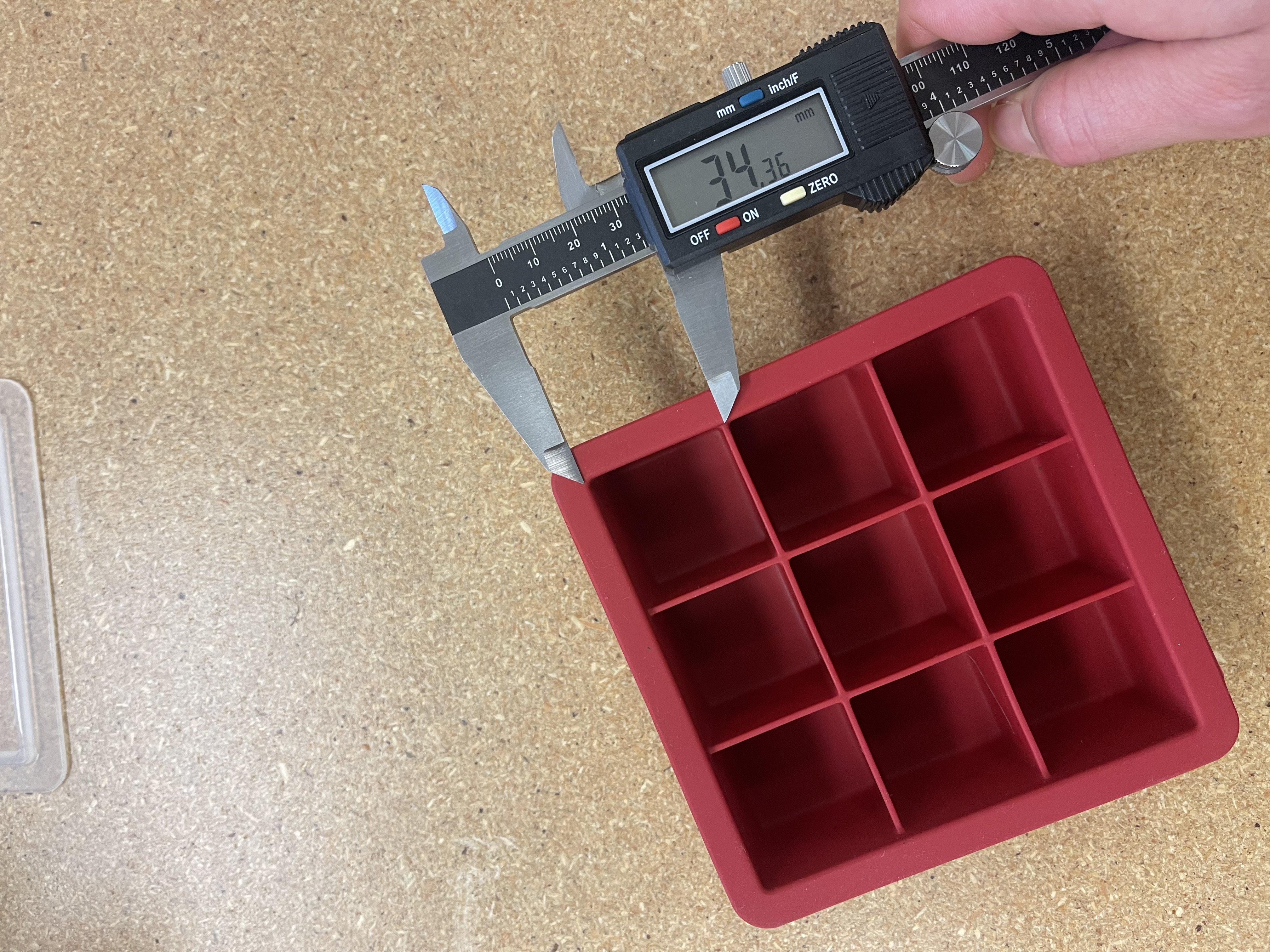
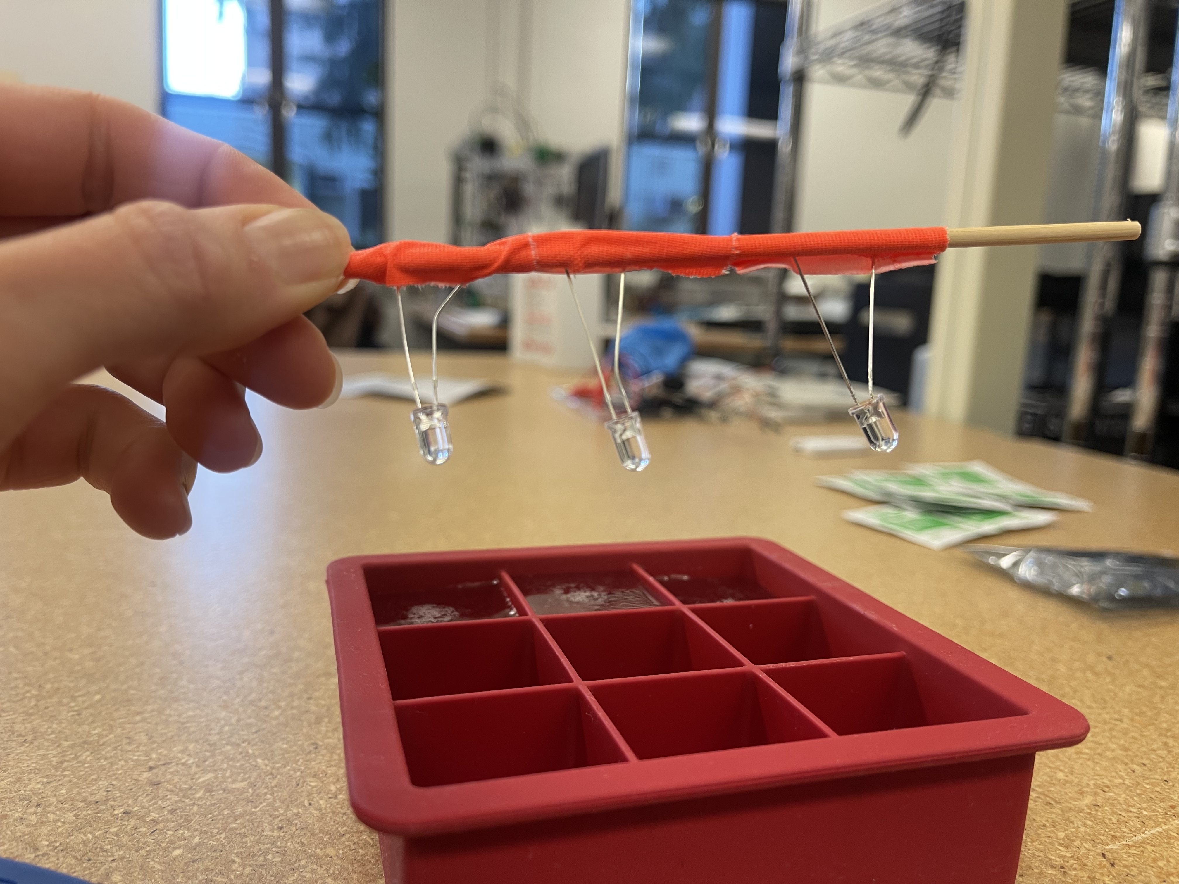
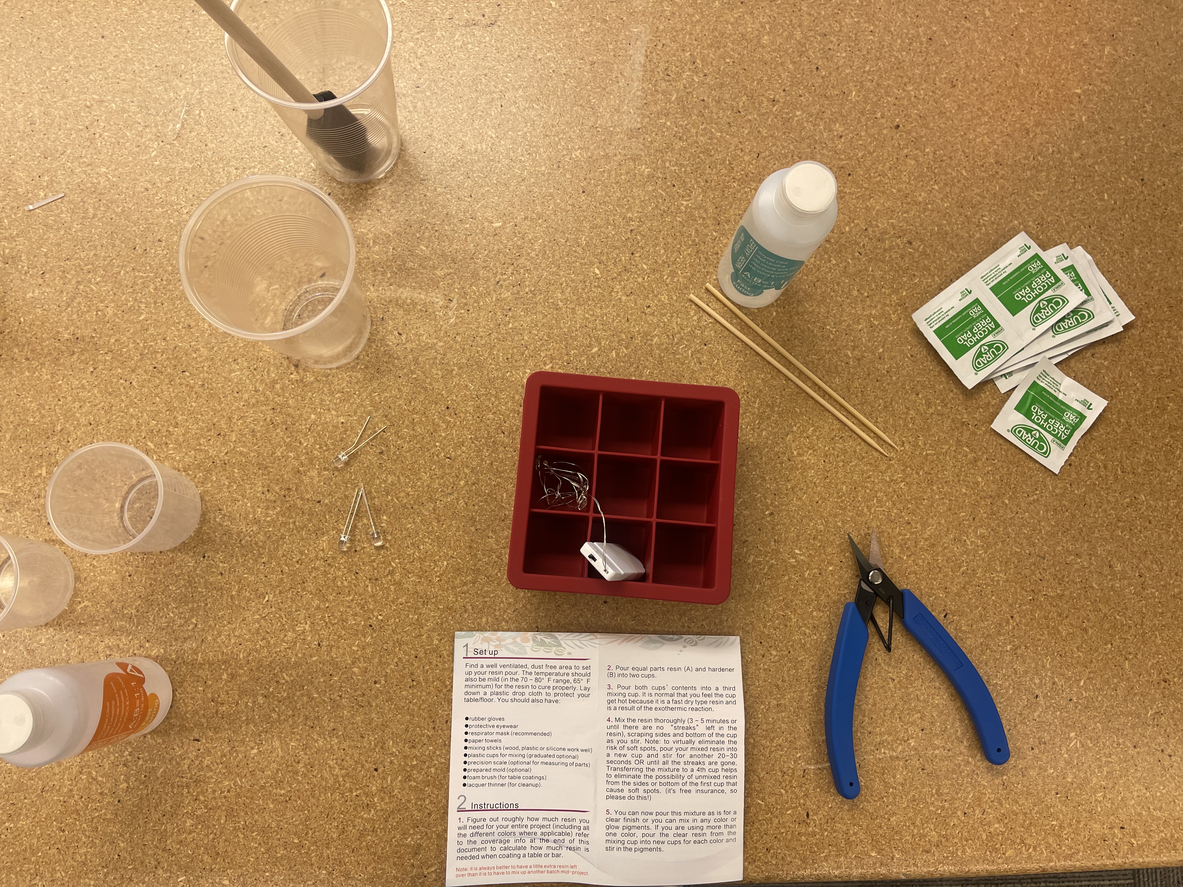
Getting ready!
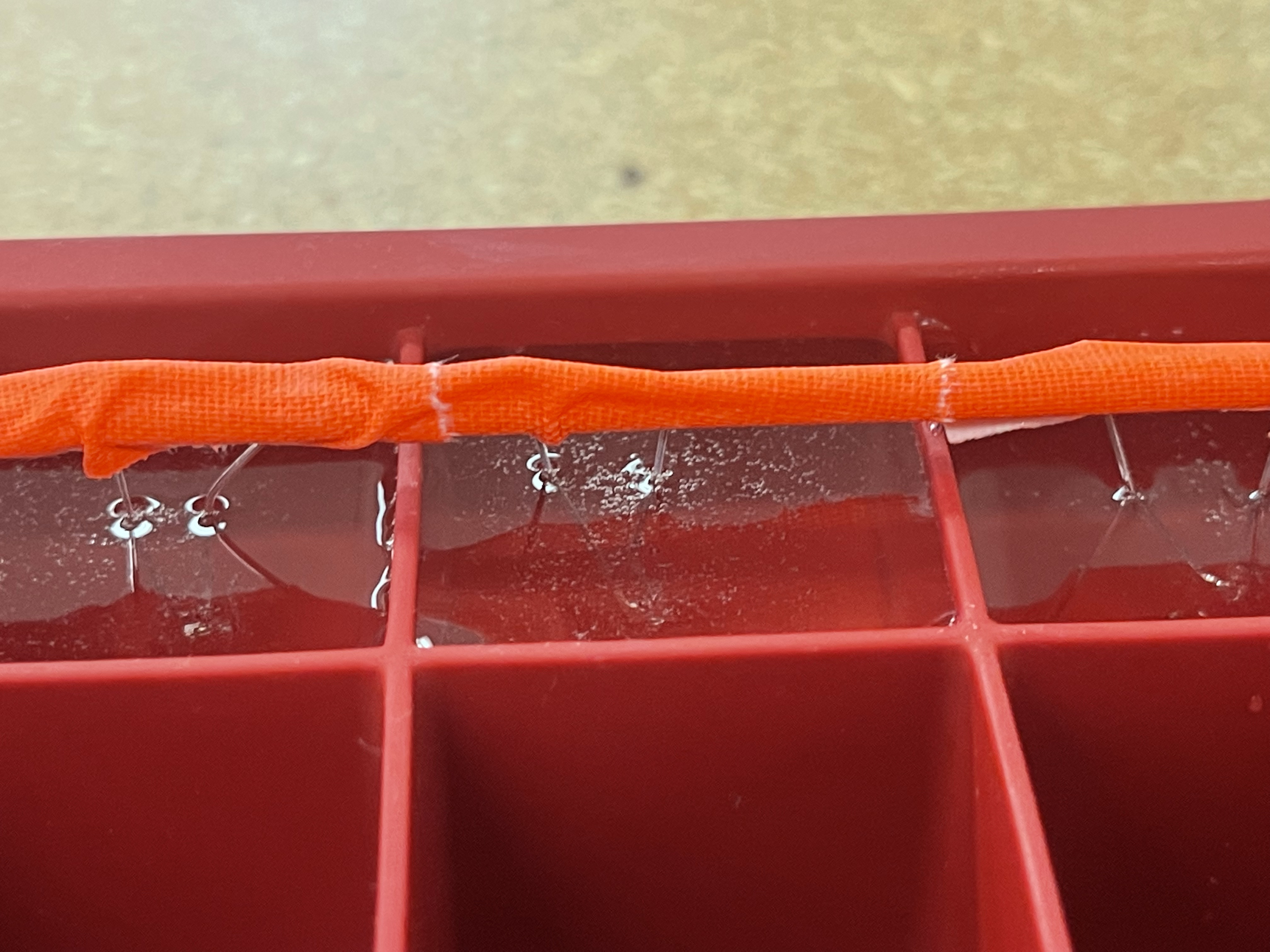
Waiting for 24 hours...
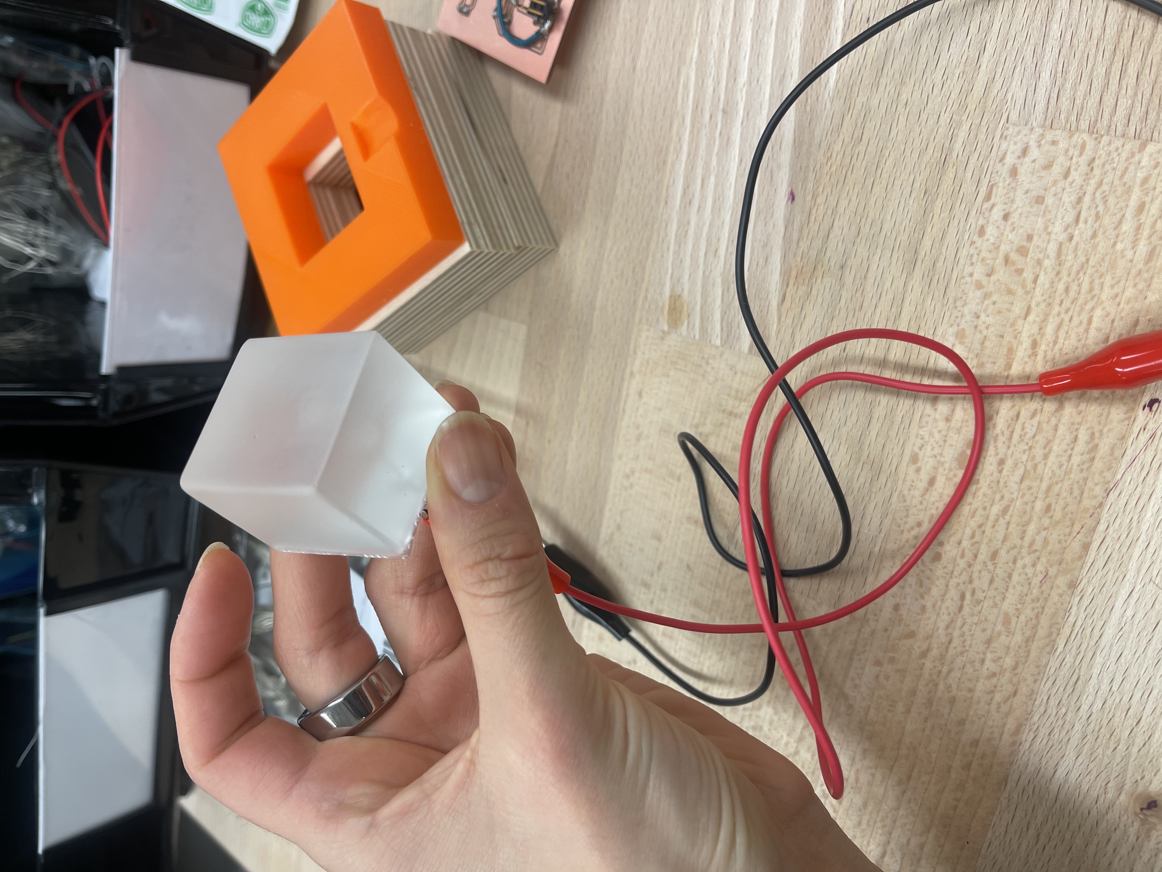
Worth the wait!
The case: fits and tolerances
The case ended up being the trickiest part of this project! Mainly because I didn't really account for the wiring and my final versions of the case were too small.
I made two versions for the case: a wooden case, milled with the Shopbot, and a PLA case, 3D printed on the Prusa.
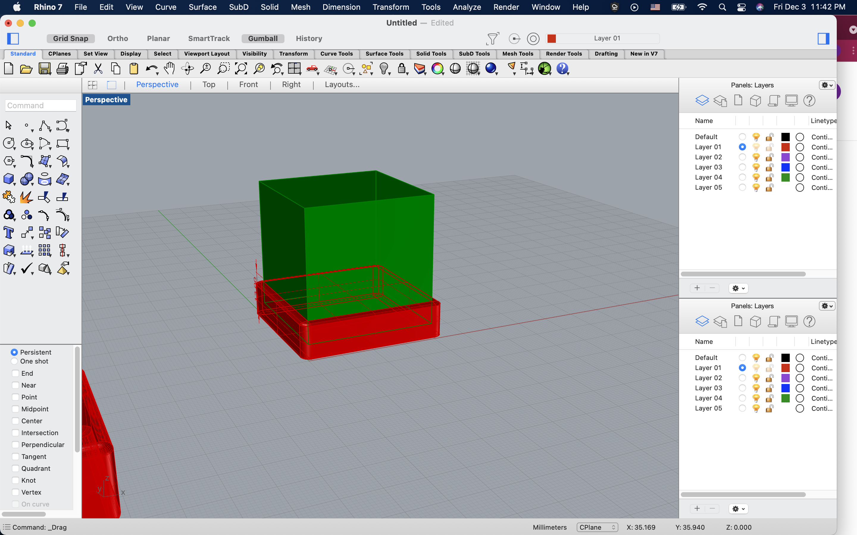
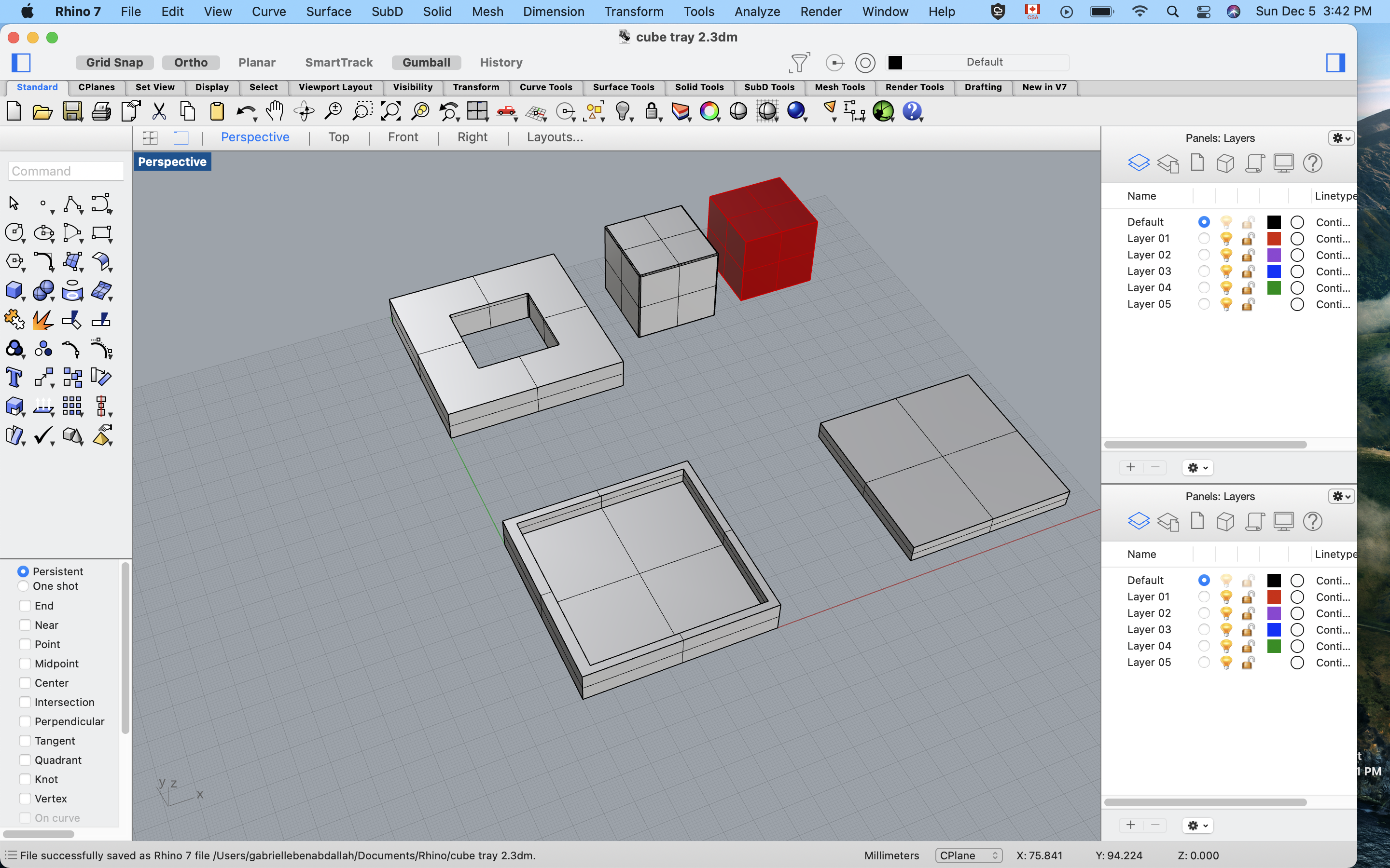
I made many iterations on Rhino, trying to figure out the right tolerances for the PLA version, and the right profile cuts for the Shopbot.
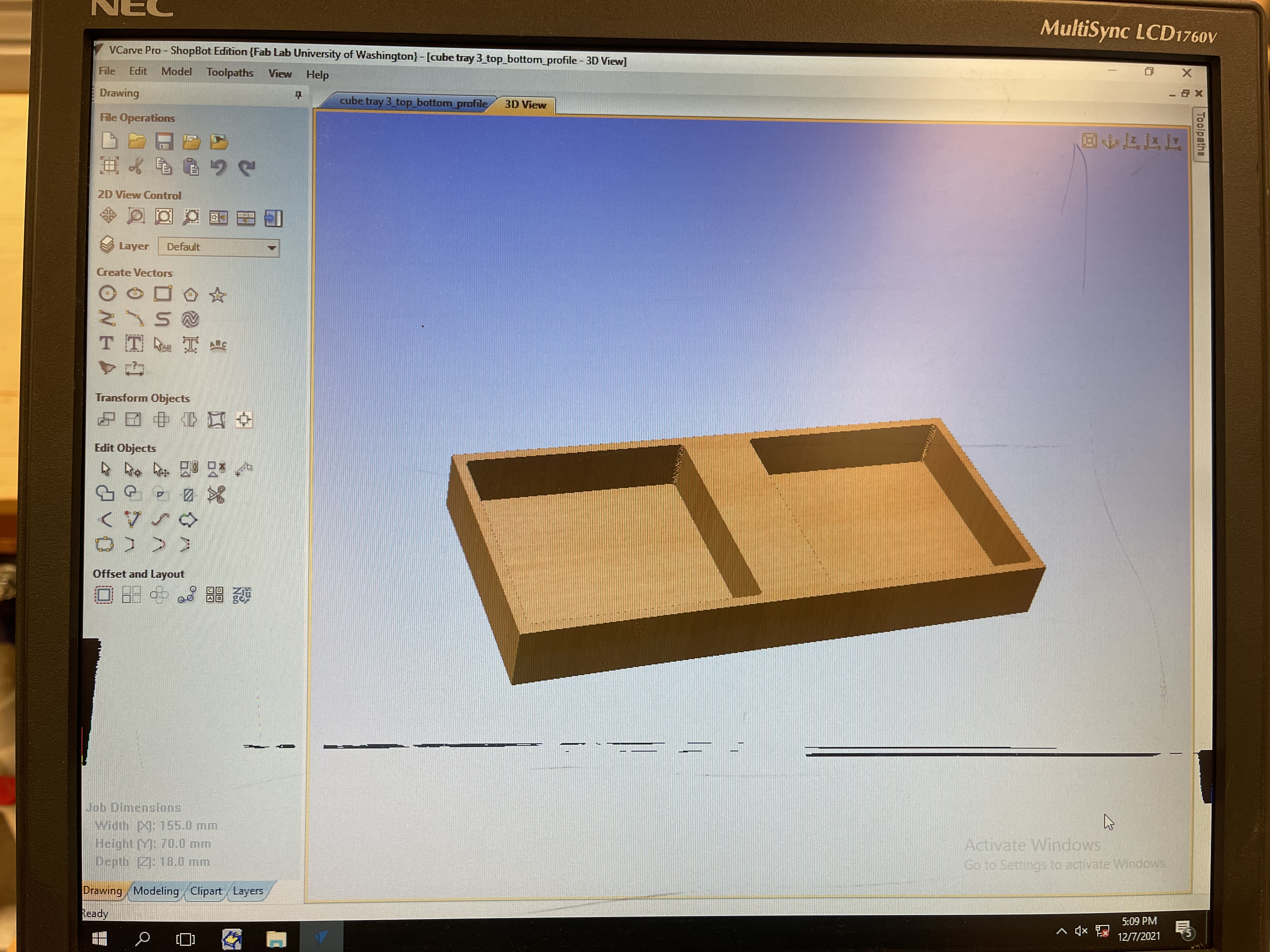
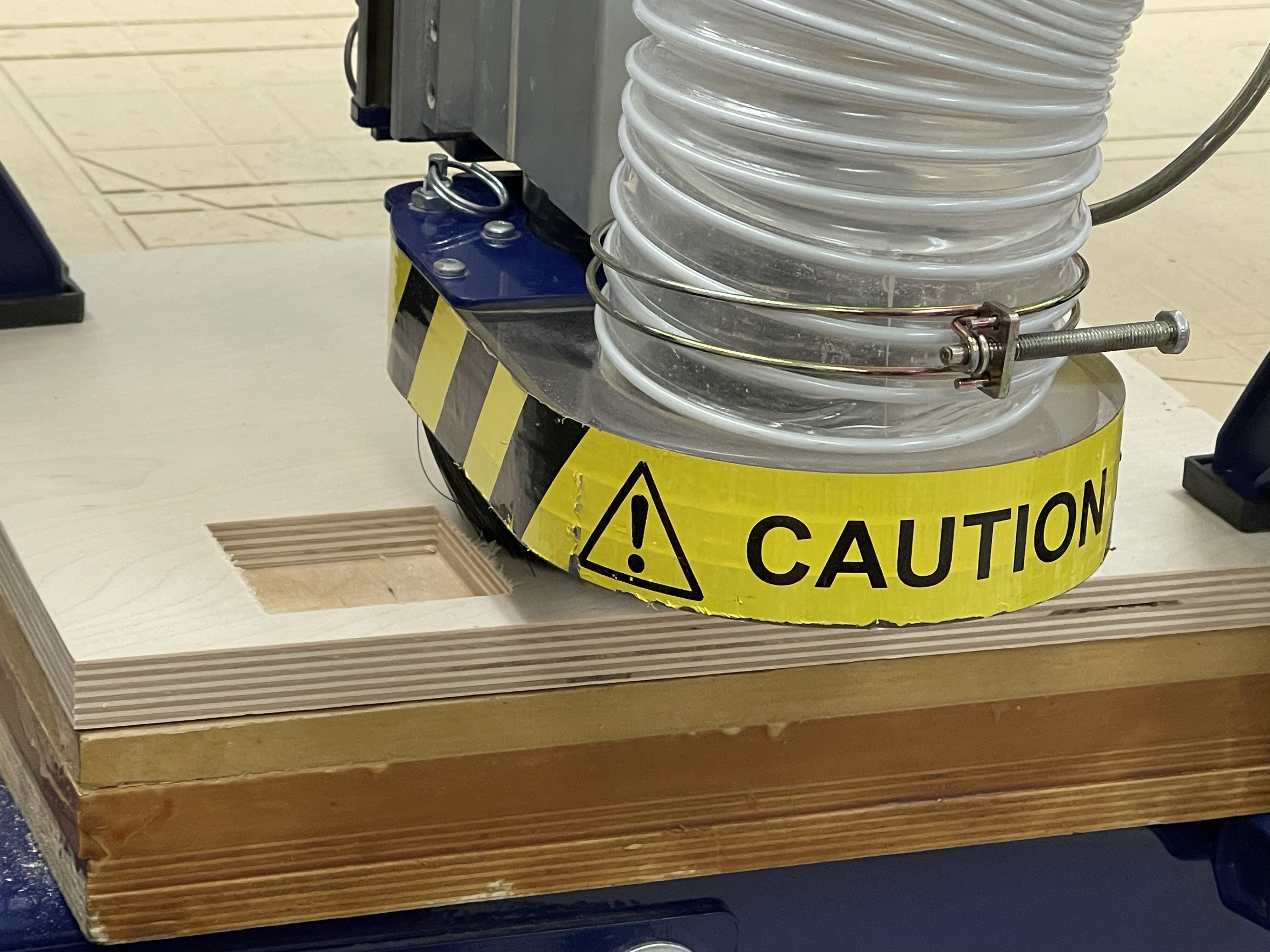

Shopbot adventures!
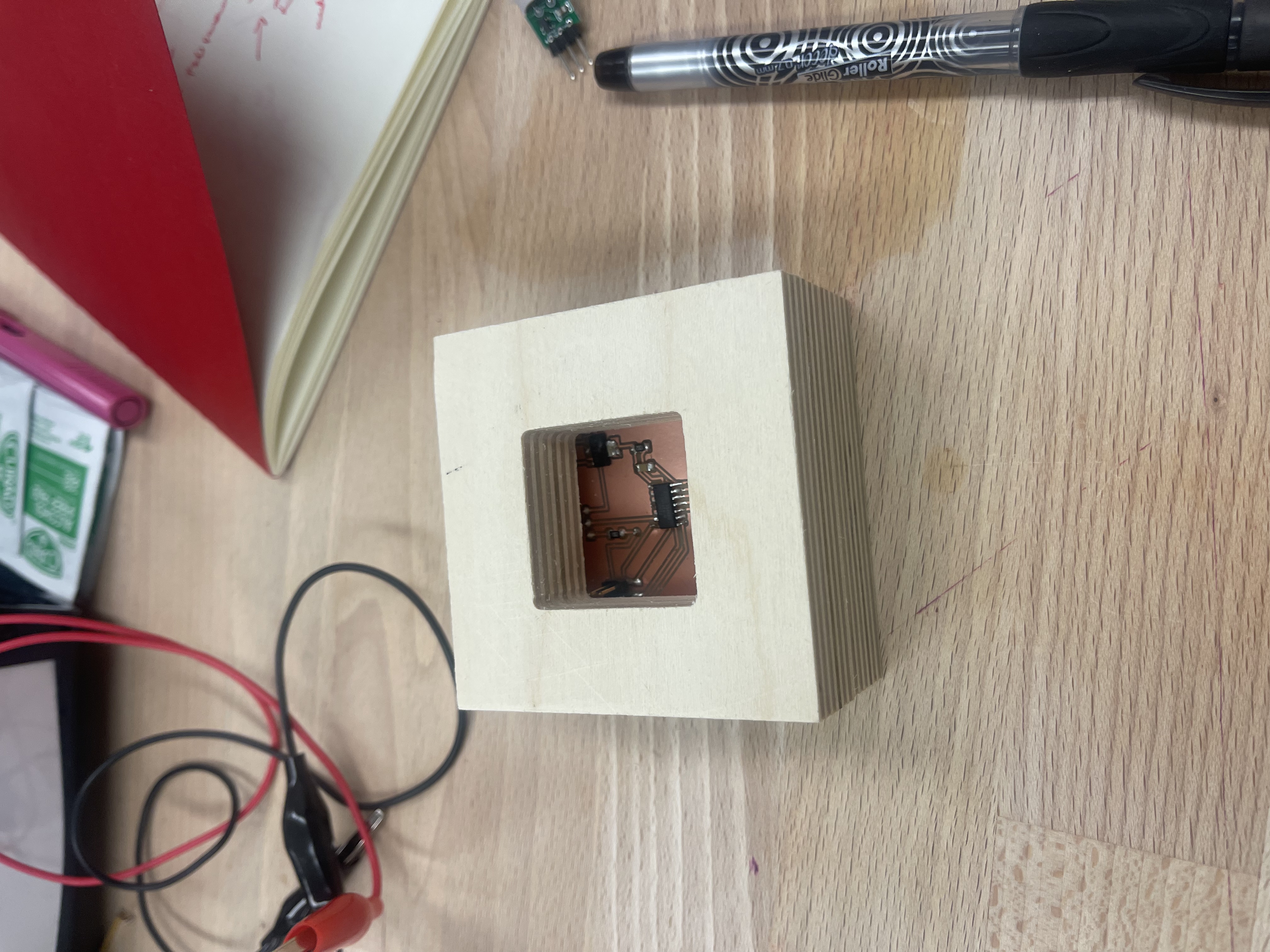
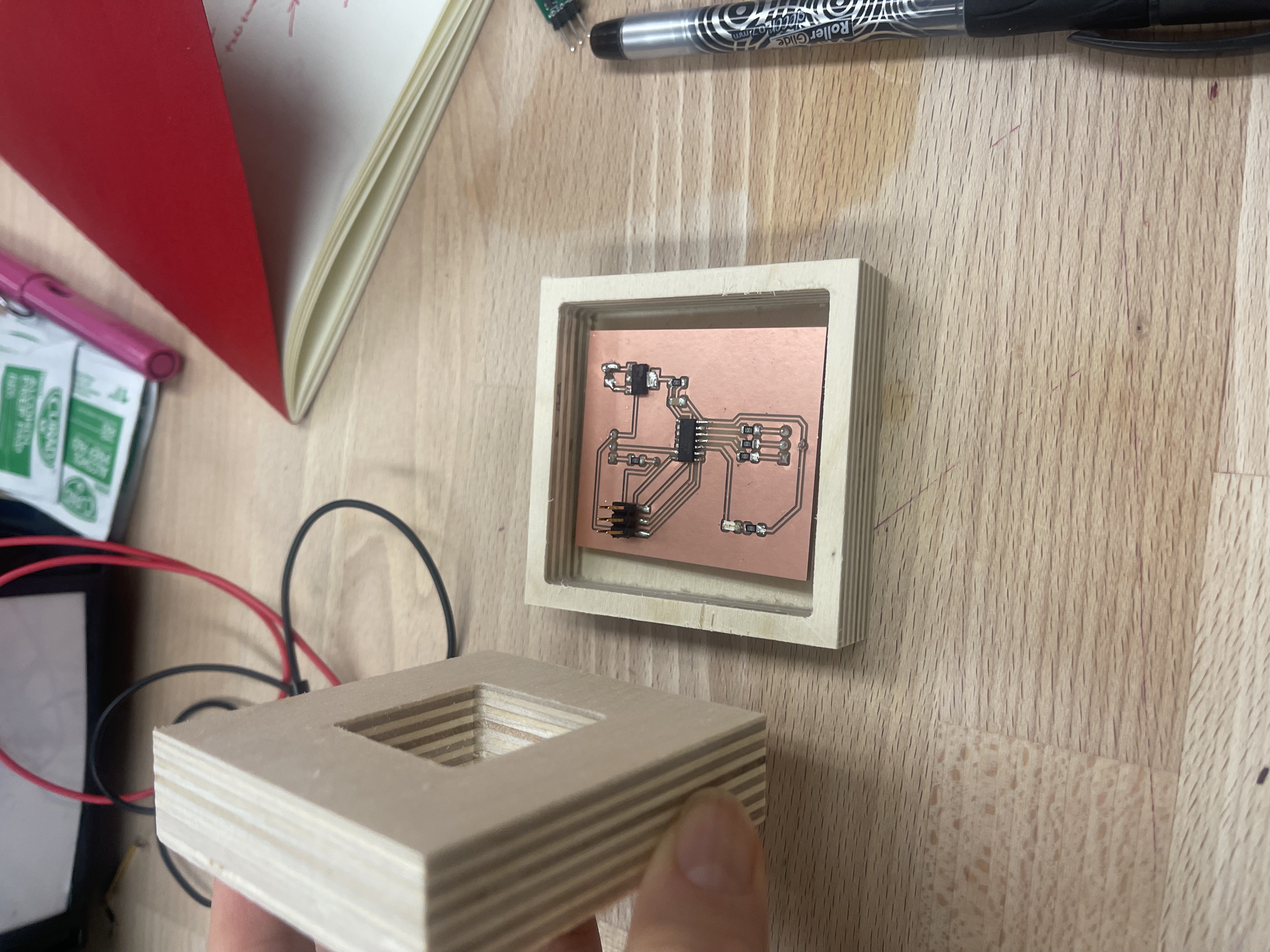
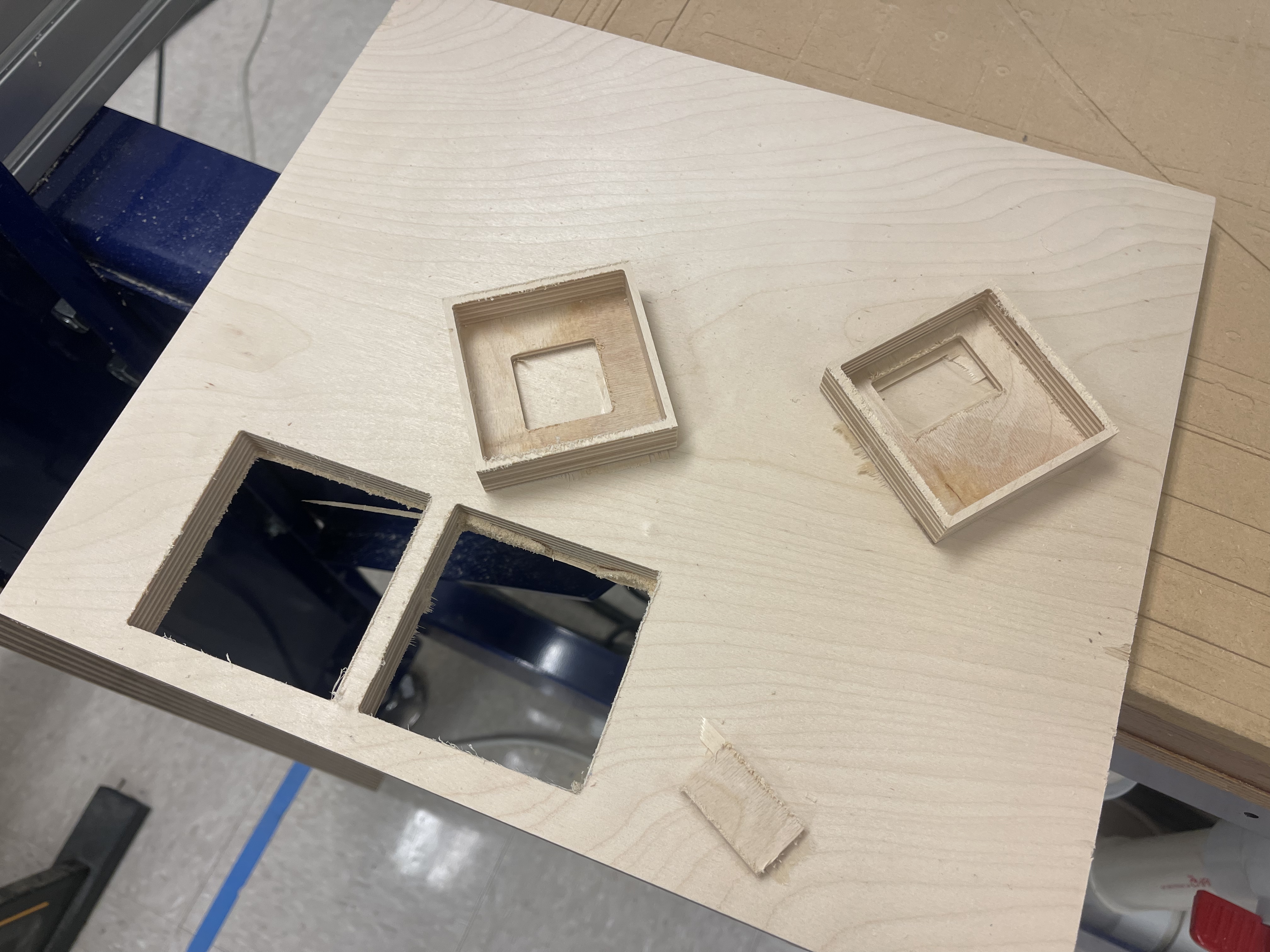
The final result, first round! However, the box didn't have the hole for the sensor. Nadya suggested I drill one at the Mill and that's what I did.
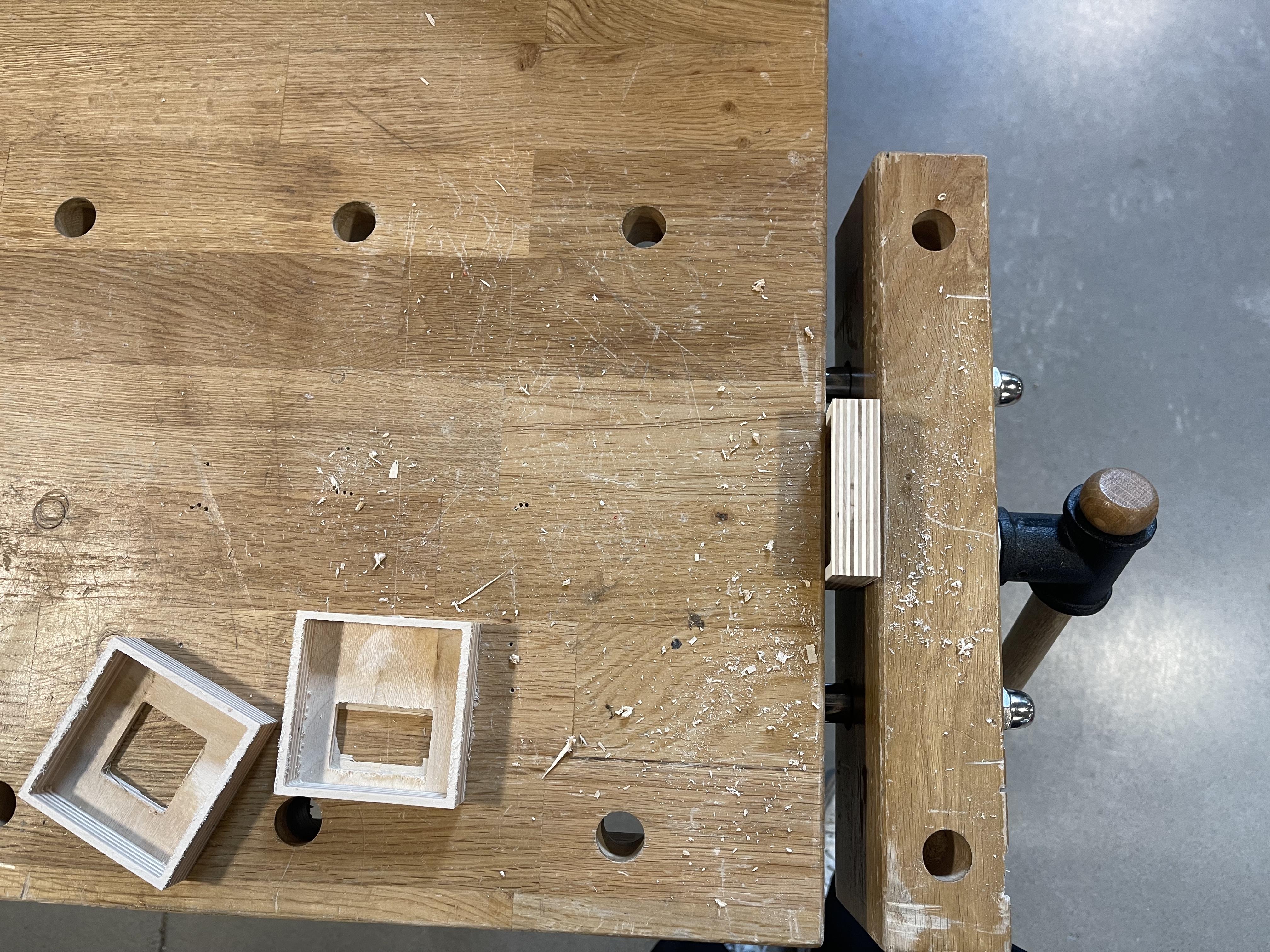
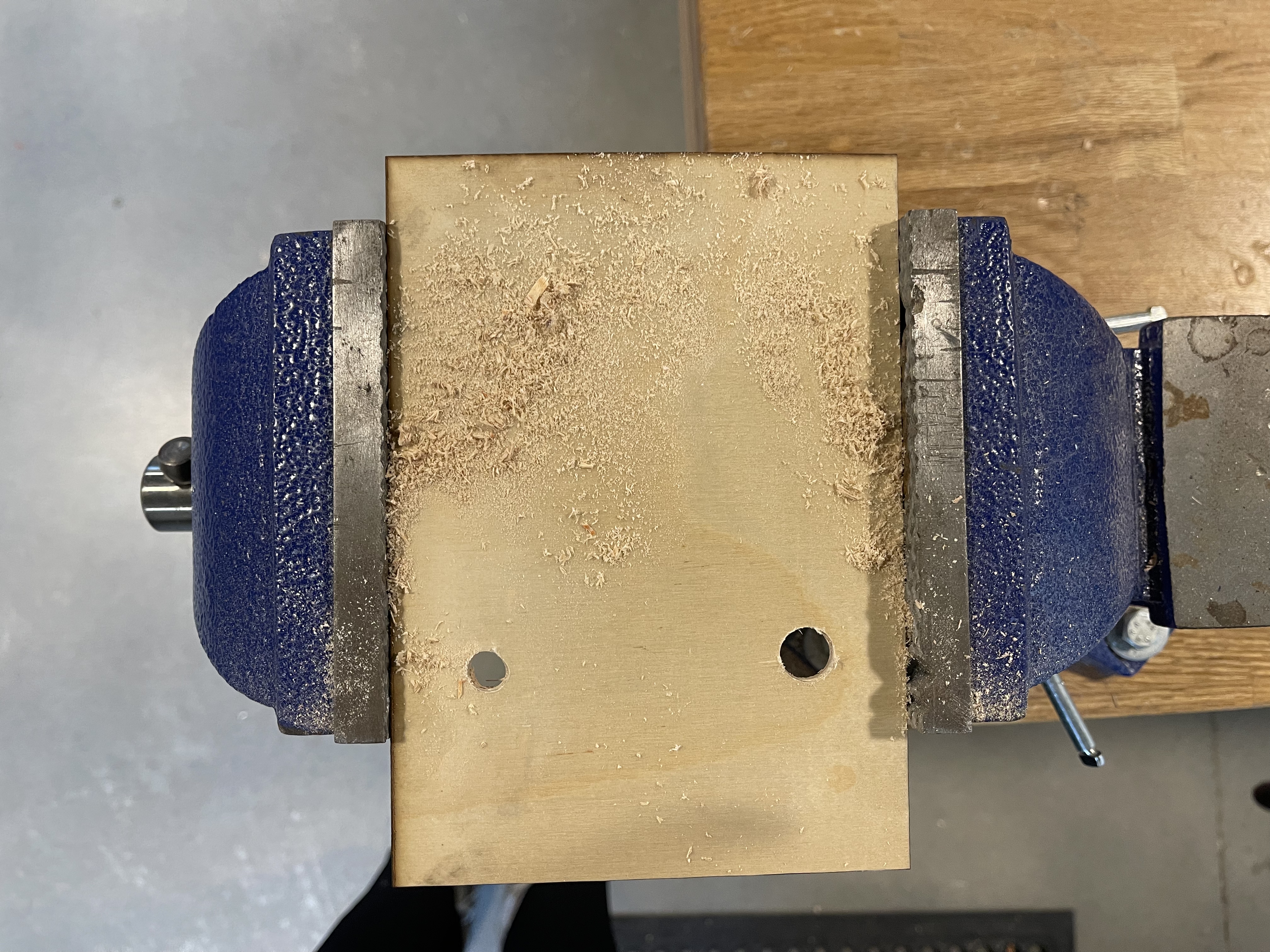
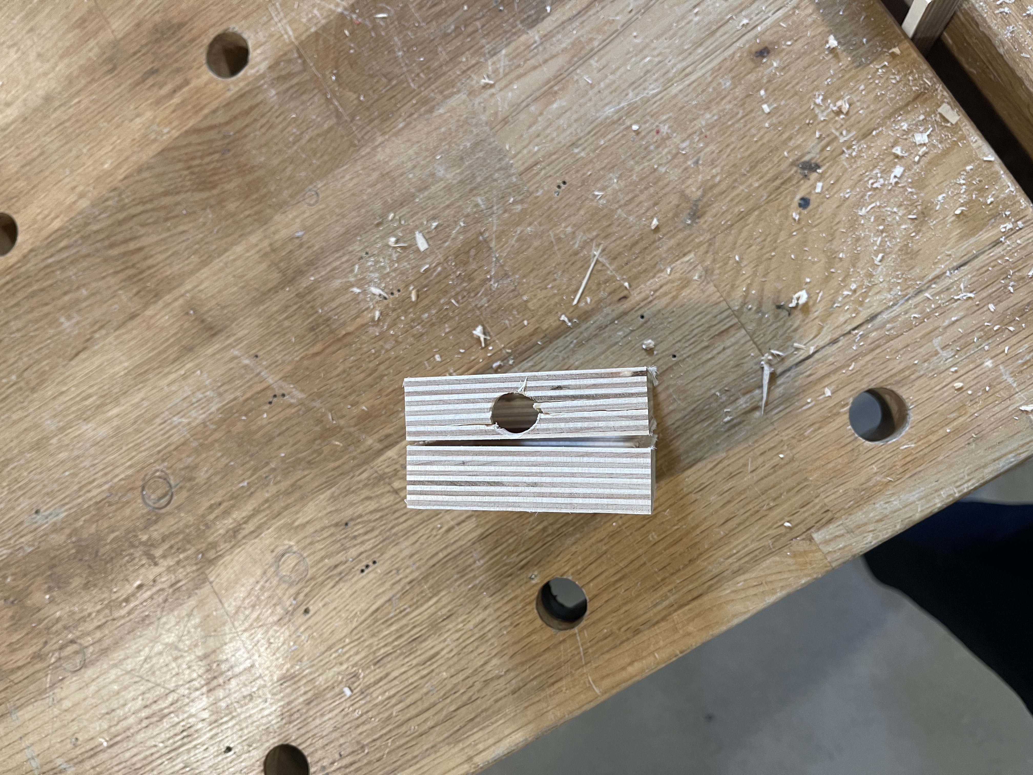
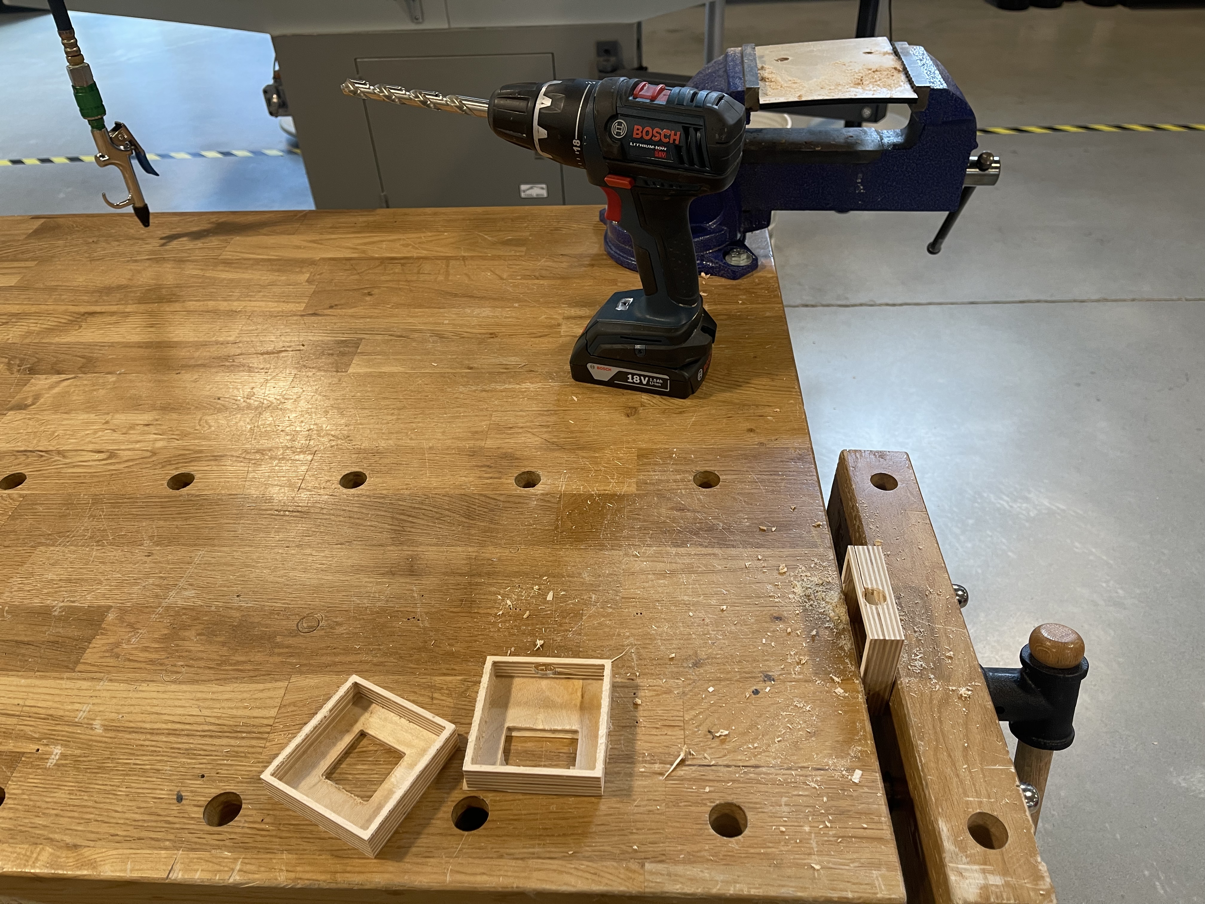
I was pretty excited about using the drill. It was the second time I used a drill in my life I think, and I honestly can't remember the first time. All that excitment made me focus more on the drill itself than what was happening to my box. I chose a big drill bit but it cracked the side of my box. Oh well. Now I know!
Then I learned about crush ribs. I'm so into crush ribs now. I learned about them in this Hackaday post. I also learned that the method I was previously using the get the right tolerance has a name! It's called the Goldilocks approach. Somehow it felt very validating to know that even more experienced makers were using this trial and error technique (which I wasn't even considering a technique before, just a kind of fumbling in the dark).
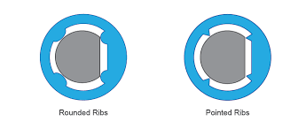
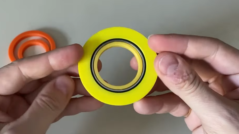
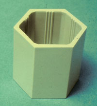
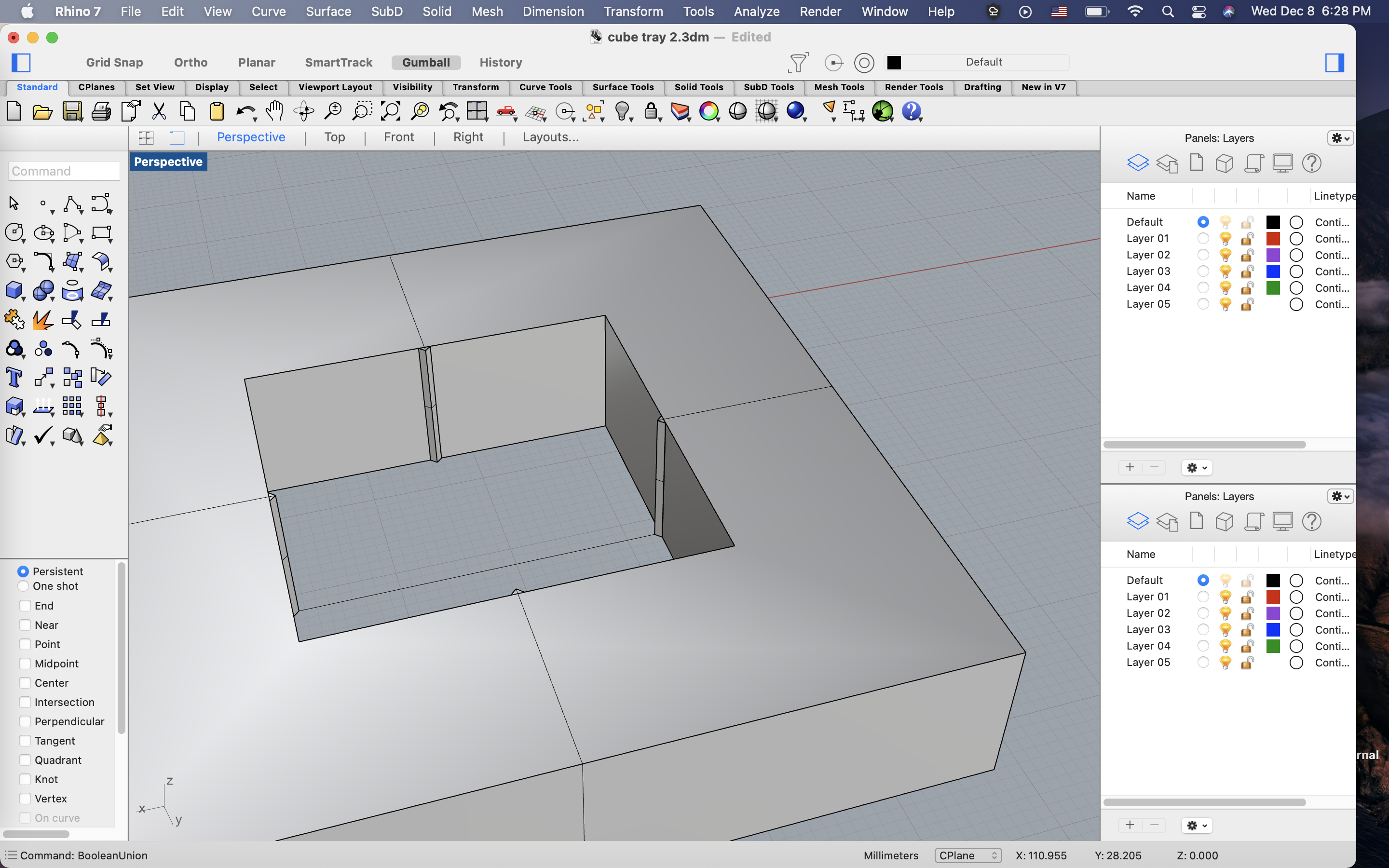
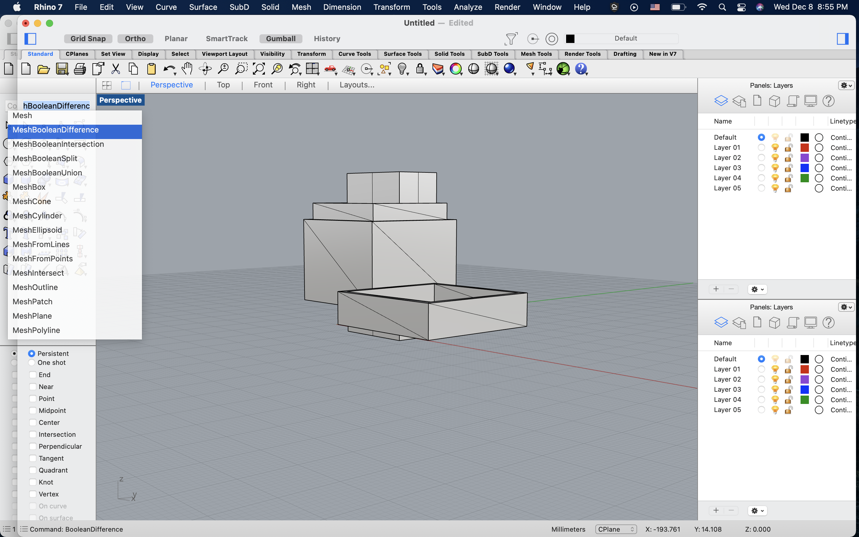
Even though I'm excited about crush ribs, I still didn't get the expected outcome. I need to finetune my technique. In the end, I decided to go with a Thingiverse design that I modified in Rhino (meshy!). I didn't get to print it though because the Prusa was acting up and it was too late at this point for calibration. So! I had to work with what I had, which was a lot of similar, not-quite-optimal parts.
Final steps: Assembly
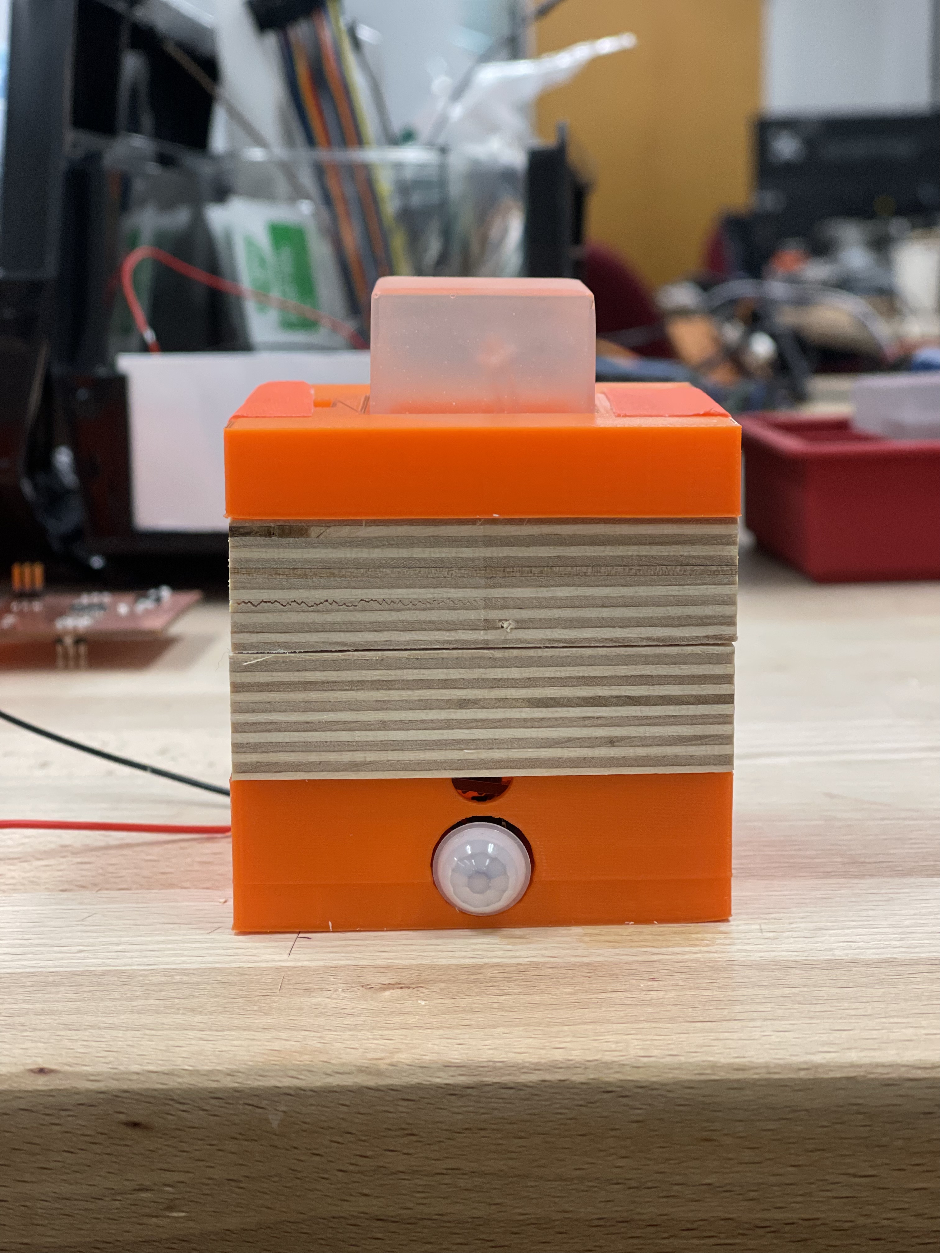
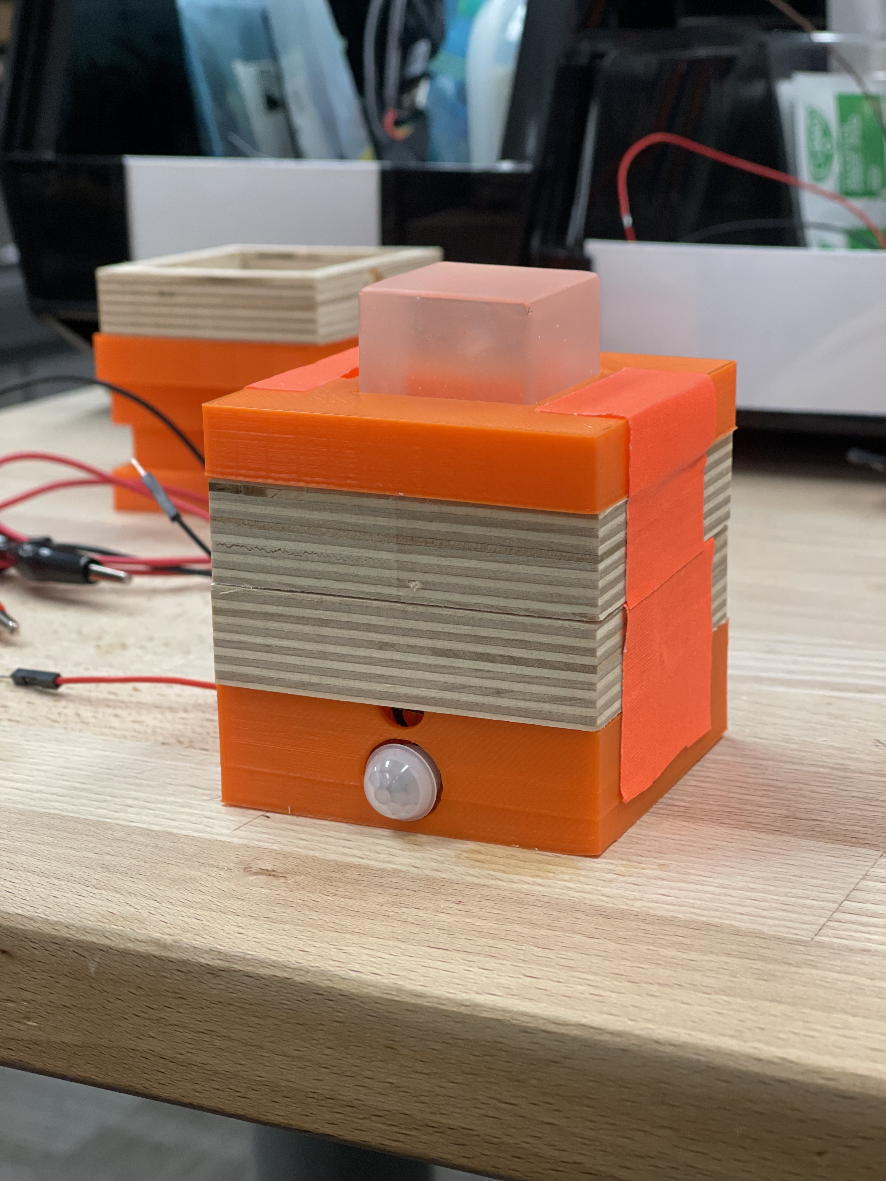
In the end, I stacked the parts I had to create a box with the desired height. I taped them together because I didn't have hot glue, but also so that we could still open the box and look inside (and debug if necessary). I'm actually pretty happy with its look! It's not a final version but it's still viable.
In the end
I learned so much doing this project, even though the outcome isn't exactly as expected or even technically impressive. I learned about electronics and circuits, cnc milling toolpaths, fits and tolerances (crush riiiibs <3), resin casting, hole drilling, the behavior of different materials, PIR and distance sensors, and programming in C. I also became a much more confident CAD-er in the course of this project/quarter. And most important of all, I have developed troubleshooting mechanisms. I think that is the key to being a good or more confident maker. Because things often don't work the first time (unless you're Nadya) and what will make the difference in the end is knowing how to troubleshoot and debug.